Continue to Site

Welcome to our site!

Electro Tech is an online community (with over 170,000 members) who enjoy talking about and building electronic circuits, projects and gadgets. To participate you need to register. Registration is free. Click here to register now.

  • Welcome to our site! Electro Tech is an online community (with over 170,000 members) who enjoy talking about and building electronic circuits, projects and gadgets. To participate you need to register. Registration is free. Click here to register now.

Measure Capacitor

Status
Not open for further replies.

AtomSoft

Well-Known Member
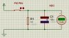
Hello all, I did a search and couldnt find anything good so far. I want to understand how to measure the size or capacitance of a capacitor.

I seen a couple PIC example that use the Comparators in it to measure it but no one really explains how everything works. Also most if not all code is ASM or HEX already so im stuck!

Can someone either point me to the right place to help me understand how and why this works and also... i see LC PIC meters which measure capacitance and inductance. But have a switch to select between the 2. Why not just use a LM339 which has 4 comparators and then a PIC to be able to show both at the same time?
 
You want to automate the measurement with a processor (ie, build a measuring device), or do you just want to measure a single capacitor?
 
Charge the capacitor to 5 volts. Then, with a timer, measure how long does it take to discharge the capacitor to 1.85 volts (37% of the initial value). If you discharge the capacitor through a constant resistor (conected across the capacitor), then the capacitance is C = T/R. I believe you can use the PIC comparator to stop a timer when the voltage drops below the 1.85 volts. The equation comes from the time constant T = C*R, which tells how long does the rc-circuit take to reach 63% of a step function.

If you discharge the capacitor with constant current, then the capacitance is C = (I*T) / (5V-1.85V). In this method, you can choose the initial voltage and the discharge voltage more freely, but you need a good constant current circuit to discharge the capacitor.
 
Last edited:
build a measuring device :D

hi atom,
Do you have any particular type and range of capacitors in mind also which parameters are you testing for.?

Pleased to see that you are buzzing....;)
 
heh um... mostly ceramic caps like small sized since they have no markings. Like 0603 and 0805 package now actual values from.. 10pf to 1uf hopefully ...

is that range ok to do ? Im just looking to find actual value. I tend to drop things and mix caps heh. So i would like to organize my collection in zip bags.

Also can i test Polarized caps? but the smd type i think they are called tantalum or something like that. They are small usually yellow package sized 1206 or something like that.

"buzzing...." ?
 
Last edited:
If I were building a test rig, I would measure the capacitor's leakage and its effective series resistance as well as its capacitance. A lot of "surplus" capacitors are unmarked rejects from a production line that were rejected because they didn't meet the leakage/esr spec.
 
Last edited:
I buy in bulk from mouser. So i know the values and all info when i get them but as stated i tend to be messy. Also i pull parts from other things i find. Like a old old old cell phone i took off a ton of caps "tantalum" and some are small and have little markings and some are large where i can read the markings. Good tantalum caps are expensive like $2 each. So why pay and waste when i can reuse heh. Since most are 10uf and up like 200uf there are good for a long time i suppose.
 
How exactly should i connect these?

I can see the voltage drop slowly in this sim. SO i have to count how long it takes to drop to 1.8v?

capa-jpg.48811
 

Attachments

  • CapA.jpg
    CapA.jpg
    22 KB · Views: 389
heh um... mostly ceramic caps like small sized since they have no markings. Like 0603 and 0805 package now actual values from.. 10pf to 1uf hopefully ...

is that range ok to do ? Im just looking to find actual value. I tend to drop things and mix caps heh. So i would like to organize my collection in zip bags.

Also can i test Polarized caps? but the smd type i think they are called tantalum or something like that. They are small usually yellow package sized 1206 or something like that.

"buzzing...." ?

hi atom,
Another common way is to measure capacitance is to make the 'C' under test, the timing component of a simple oscillator, count oscillations over a period say of 0.1s or 1sec and then calculate the capacitance value.

BTW: I see that the word 'buzzing' didn't get exported from the UK to the USA.
Its basically means busy and productive in what you are doing, I guess it was derived from the busy bee which is always buzzing.;)


EDIT:
added pdf's
 

Attachments

  • esrmeter.pdf
    119.1 KB · Views: 383
  • LCF[1].pdf
    538.3 KB · Views: 152
Last edited:
I get buzzing now heh... just havent really heard it in a while.

Can you try to explain that more to me about the "Another common way is to measure capacitance is to make the 'C' under test, the timing component of a simple oscillator, count oscillations over a period say of 0.1s or 1sec and then calculate the capacitance value."

I dont understand it

hi,
Check my last post EDIT addition.!
 
Read this FAQ on Capacitor Testing.
 
ESR is mostly to check if the capacitor is in good condition. Which is well to have but not needed. Just confused me a bit more :D Also that FAQ doesnt help really.

The most usefull part was:

Alternatively, using a DC power supply and series resistor, capacitance can be calculated by measuring the rise time to 63% of the power supply voltage from T=RC or C=T/R.

So would this be right? If i use 5v and a 10bit ADC then is 0v = 0x00 - 5v = 0x3FF... so 63% would be 644 (0x284)..

so i have to count how long it takes to for the result to reach 0x284 then divide it by the resistance used?

So lets say:

T = 100ms
R = 100k

So if I do

T/R = 0.000001 F
aka 1uF
Correct?

also to test this T=RC =

.000001 * 100000 = .1s (100ms)
 
Last edited:
I see a couple of problems. I would use the comparator (not the ADC, which takes too long to measure the decaying voltage). Set the comparator to an internal reference of ~1/3Vcc to 1/2Vcc. Set the comparator to interrupt when the decaying voltage across the capacitor goes below the reference. In the ISR, grab the timer value that exists at that moment.

To charge the capacitor, use a port pin which is always set HIGH. To release the capacitor to begin discharging, set the TRIS for the port pin to INPUT. In other words, the port pin is either HIGH or OFF. Zero the timer concurrent with when the Port pin is switched.

It doesn't matter that the trip point of the comparator is exactly 1 time constant. You can just adjust for this in the math.
 

Attachments

  • DF115.png
    DF115.png
    40.7 KB · Views: 159
Last edited:
Status
Not open for further replies.

Latest threads

Back
Top