Continue to Site

Welcome to our site!

Electro Tech is an online community (with over 170,000 members) who enjoy talking about and building electronic circuits, projects and gadgets. To participate you need to register. Registration is free. Click here to register now.

  • Welcome to our site! Electro Tech is an online community (with over 170,000 members) who enjoy talking about and building electronic circuits, projects and gadgets. To participate you need to register. Registration is free. Click here to register now.

Maxell CR2032 Battery Backup

Status
Not open for further replies.

Gayan Soyza

Active Member
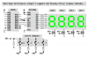
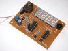
I have a clock done using a PIC (5V). It uses 4 seven segments. For the battery backup I'm using a CR2032, 3V coin cell. When power goes down the battery will keep up the time. In battery backup mode the 4 segments are disabled by the design. So only the PIC is working in backup mode.

The problem is CR2032 Battery will give power to the PIC via a diode (1N 5817).
So the voltage will reduce more.

What’s your idea on this method? How long will this battery works?
 
Energizer shows that their CR2032 lithium coin cell can power a 15k resistor for 900 hours then the voltage will be 2.8V.

I don't know what is the backup current of your PIC and I don't know if it can work with a supply of only 2.5V.
 
Read the processor datasheet, see if you can put the PIC to sleep and leave just the timer run. When the timer overflows it will wake the PIC adjust the time and go back to sleep.

I only read about this. I use RTCC clock chips.

EDIT: If there are other chips drawing power you might want look at ways to turn them off when on battery power. Depending on the pic you can get down into the low uA range.

3v0
 
Hi 3V0 thanks for your input.

I was thinking about that, but unfortunately I couldn’t find any spare wakeup events all my PIC all pins were used :D & all my timers derived from processor functions :(

So the micro controller is working all the time with a simple built in timer. I’ll check out how this coin cell battery is last longer.
 
Last edited:
You are between a rock and a hard place.

The only other thing I can think of is running the PIC as slow as the applicaiton will allow to reduce the power it uses.

But I will guess you can not slow it down any.

Maybe next time start with a PIC that has a few extra pins.
 
Hi Gayan,

If you're not using an RTC chip then this might have been the perfect opportunity to use the low power oscillator and a 32768 Hz watch crystal.

You could run on the 4 or 8 MHz INTOSC and use an interrupt service routine to drive your displays and use a 1 second Timer 1 'overflow' interrupt to update your RTC variables. When you detect loss of main power you simply turn off the displays and goto "sleep". The lower power Timer 1 oscillator continues to run during "sleep" and wakes up the microprocessor on Timer 1 overflow. At that time you would simply update your RTC variables, reset bit 15 on the TMR1 register pair (for 1 second overflow), and go back to sleep.

Mike

Hi mike thats also a nice solution but needs some splitting between two ports.So the code gets little bit messier :D I'll try do do a similar thing on my next design.Thanks for the idea sir.
 
Ok guys I have managed to reduce the power consumption as much as I can.I've reduce down to 125uS during the main DC power supply failure.

I like to show you some pictures of my design.
 

Attachments

  • Clock Full.JPG
    Clock Full.JPG
    2.8 MB · Views: 365
  • Top.JPG
    Top.JPG
    2.8 MB · Views: 266
  • Bottom.JPG
    Bottom.JPG
    2.8 MB · Views: 285
Very nicely done indeed!
Feel like building me one of those 3.5 digit thermometers? :)

I would just need the logic part. I want to boost the output for each LED segment and have an LED readout thermometer on my shop with 10 inch high ultra bright LED digits!:)
In Farenhight of course!
 
What did you base the highly accurate part on? =) Not to be a stickler, but I am.
 
Hi mike thats also a nice solution but needs some splitting between two ports.So the code gets little bit messier :D I'll try do do a similar thing on my next design.Thanks for the idea sir.

Yes, you're right. The Timer 1 oscillator pins are on RB6 and RB7 on a 16F88. You'd have to split the ports and you might end up short of pins.

If I ever get around to trying it I think I might do it like this;

k8lh-4-digit-display-png.28031


RB0 through RB4 are used for the display and RB5 is used for the switch inputs. RB6 and RB7 can be used for the Timer 1 oscillator function. This leaves RA0 through RA7 available for other functions.

Food for thought...

Mike
 

Attachments

  • K8LH 4-Digit Display.PNG
    K8LH 4-Digit Display.PNG
    38.9 KB · Views: 1,274
Hi Mike thats a nice way of doing.Thanks for your idea.Its really helpful for future upgrades.

I always see every time you taking those expensive "mircrel" or "allegro" components which doesn't available in rest of the world :D

Actually how much are those?
 
Hi Gayan,

I didn't realize those devices were difficult to obtain.

Digikey sells them in the DIP-16 or SOIC-16 package for 2.43 USD (quantity 1). A less expensive alternative might be a 74HC595 and eight P-FETs.

Mike
 
Last edited:
Hi again Gayan,

There seems to be a much larger selection of serial-to-parallel sinking driver ICs (TPIC6C595, MIC5821, etc.) which seem to have better pricing too. These would work great with PFET column drivers on command anode displays.

Mike
 
Status
Not open for further replies.

Latest threads

New Articles From Microcontroller Tips

Back
Top