Continue to Site

Welcome to our site!

Electro Tech is an online community (with over 170,000 members) who enjoy talking about and building electronic circuits, projects and gadgets. To participate you need to register. Registration is free. Click here to register now.

  • Welcome to our site! Electro Tech is an online community (with over 170,000 members) who enjoy talking about and building electronic circuits, projects and gadgets. To participate you need to register. Registration is free. Click here to register now.

Making a realy latch

Status
Not open for further replies.
Sorry Len, no it wont be used in a vehicle.

The PIC im using is pre-programmed, Ive not dabbled with programming yet.

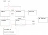
As I said above, a block diagram would help me to understand what you're doing so I can make more definitive suggestions.

PIC programming is fairly easy to learn and reduces the need for hardware.

I learnt PIC programming from a book written in the UK:-

"PIC Your personal introductory course" by John Morton.
 
Last edited:
Thanks I will look up the book.

The thing is I havent really got much spare time at the moment, and to learn + re-write all the code that I have on the PIC would take me a long time.
 
Thanks I will look up the book.

The thing is I havent really got much spare time at the moment, and to learn + re-write all the code that I have on the PIC would take me a long time.

Yes, I understand.

However, you should not have to re-write all of the code. It should be just a modification, possibly, just a sub routine.
 
I've spoken to someone where I work and i asked them if there was a way to extract the code from the PIC and they said that it has probably been locked?
They didnt say locked I cant rememeber the exact term but thats what I think they meant :(
 
My recollection is that the term is Code Protection.

To find out if it is, you would have to use a PIC programmer to read (or attempt to read) the code.
 
I will get something drawn up :)
You wrote this in your last post re the hardware, I need a circuit or block diagram before I can help further.

The verbal description is not adequate. Someone once said "a picture is worth a 1000 words"

As for the PIC possibility:-

You can buy PIC programmer kits.

I can advise you on where to buy a suitable kit if you wish.

If the code is protected, you could buy a PIC and write your own programme.
 
Last edited:
The dual relay solution is interesting but isn't it cheaper to just use a single relay, a transistor and a flip-flop IC?

Hi Hero999,

it depends on what are your planning concerning power consumption. A bistable (latching) relay consumes power only for a short moment when conacts are thrown. (It wouldn't make much sense to use a permanently energized relay in an 'anti-standby-switch'.)

Bistable relays aren't much more expensive than a single relay. Check out the FINDER 40,52 series (single coil, 12/24V, max 2000VA) for info.

Regards

Boncuk
 
Been pretty busy but I've just knocked this up quickly. Hope it gives you a bit more understanding as to what Im trying to achieve.
 

Attachments

  • block.jpg
    block.jpg
    136 KB · Views: 201
Been pretty busy but I've just knocked this up quickly. Hope it gives you a bit more understanding as to what Im trying to achieve.

Thanks for the drawing - what a difference a picture makes.

Some questions.
1. Why is there a connection shown between the MOSFETs & the Relay?

2. Will there be decoding spikes in the O/P3 line?

3. Do you need a "switch on at reset" function?

To answer Q2, I need more info on the Decoder. If there are decoding spikes, it will cause the FF to flip randomly, ie. if there is an odd number of spikes it will change state but if there is an even number it will appear to not toggle (because, if there were say 4 spikes it would do this 1/0, 0/1, 1/0, 1)

The reason for Q3 is because you don't need a relay Flip Flop. It can be done with a CMOS Flop Flop and 2 transistors.

But the CMOS FF will assume a random state when the power is turned on, so the display may be on or it may be off.
 
Last edited:
Hi Hero999,

it depends on what are your planning concerning power consumption. A bistable (latching) relay consumes power only for a short moment when conacts are thrown. (It wouldn't make much sense to use a permanently energized relay in an 'anti-standby-switch'.)

Bistable relays aren't much more expensive than a single relay. Check out the FINDER 40,52 series (single coil, 12/24V, max 2000VA) for info.

Regards

Boncuk
By co-incidence, I found the attachment in the latest Silicon Chip magazine.

I've erased the designer's name in case he doesn't want it spread around the internet.

Dan,
In order to use this circuit, you would need a 2 transistor level shifter. I don't recommend it as a CMOS Flip Flop will be simpler, smaller & cheaper.
 

Attachments

  • Relay latch.gif
    Relay latch.gif
    126.8 KB · Views: 242
Last edited:
No problem, sorry its not of a better quality.

1) Thinking about it that connection should not really be running through the relays, its simply a GND signal that the FETs will sink to.
2) Im not sure about spikes, when I had a scope' hooked up it looked like a fairly 'steady' signal at 5v. The decoder is a RF600D - **broken link removed**
3) I'm not sure I fully understand the question, which reset?

Thanks kindly for your time

* just seen the circuit you posted from Silicon Chip, looks a bit like the dual relay solution we had previously discussed. As you say I think the CMOS idea sounds better :)
 
Last edited:
Hi Dan,

when using a single coil bistable (latching) relay I suggest to use an MC34151 as level shifter.

Regards

Boncuk
 
1. understood

2. You would not see spikes on a scope as they are of very short in duration. I'll look at the Decoder spec after breakfast first.

3. resetting the FF.
It has 2 states 0 & 1.
When the power is turned on it is not possible to predict which state it will be in. Does this matter in your case?

The latching relay is only one relay not 2 as in my relay FF circuit. This may also need a "switch on reset" circuit added since it will remain in which ever state it was in last time the circuit was powered.

PS my 2 relay version will always start in the reset state.

Nevertheless, I feel the electronic solution is the best.
 
Last edited:
I looked at the Decoder spec and I don't think there will be any spikes in OP3.

The last question an answer to is this:-

What is the maximum display current, ie. what current is drawn from the +12V supply through the "relay" contact when the display is showing all 8s?
 
Last edited:
I see thanks for that explaination!

Thinking about it, I guess upon power up ideally the relay would be in the active state. Then you could power down from the remote.

When you say maximum display, the mosfets will sink max 6A each so I guess the maximum current going through the relays could be 18A, is that ok?

Many thanks again!
 
I now see why you mentioned an auto relay! I was not expecting that much current.

So I need to know now is the resistance of the coil of the relay you have chosen.

JayCar sell a range of auto relays. From 20 Amp to over 100 Amp.
So a 20 or 30 Amp one would suit your purpose.

As I understand you post above, you want the relay to operate when the power is turned on.

I also need to know what type of Flip Flop ICs are stocked by your supplier.
 
Last edited:
Dan,
I looked at the FF data sheets & the best choice for your purpose is the 74HC109.

Let me know if your supplier stocks it.

If not, tell which ones they do stock.
 
Last edited:
lol yes quite a large amount of current! I'm not using that much at the moment but dont want to limit the functionality of the finished controller.

Just had a look, and RS seem to have a fairly nice selection of automotive relays.

Tyco Electronics | Relays, Switches and Indicators | Relays | General Purpose Relay | Automotive Relays |V23076A1001C133

The above states a coil resistance of 90ohms, very cheap and I could include it on my PCB :) although the configuation is listed as SPCO?

Tyco Electronics | Relays, Switches and Indicators | Relays | General Purpose Relay | Automotive Relays |V23134A52X205

the above is a bit overkill, at 40A but is SPDT. It also says it 'Diode (cathode at 86)' im not sure what that means?

it looks like my supplier does stock that FF :) Texas Instruments | Semiconductors | Standard and Speciality Logic | Flip Flop | 74HC Family |SN74HC109N

Thanks
 
Dan,
Have you tried JayCar?

They have a UK mail order outlet. They may be cheaper then RS. I find RS expensive.

www.jaycarelectronics.co.uk

Search for cat numbers

Relays :- SY-4042, SY-4068 are 2 examples, they have others.

ICs :- One of the following would suffice 74HC73, 74HC74 or 74HC76 (they don’t stock the 109) Search for ZC-4829, ZC-4830, ZC-4832

And you will need a transistor such as the MPSA13, cat ZT-2287
 
Last edited:
Status
Not open for further replies.

Latest threads

New Articles From Microcontroller Tips

Back
Top