AtomSoft
Well-Known Member
Hi all....
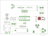
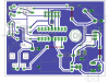
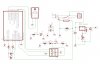
As some know i made this little IR door Opener and well.. i have the schematic made but my board skills arent good. Im trying to make it into a 1 sided board which seems impossible ... i just need some help making the board.. It can be 1 or 2 sided but im not such a neat person so can someone please help me.. Below is the schematic.. in EAGLE...
EDIT: Updated Schematic
Attachments
Last edited:
")