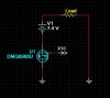
I want to use an n-channel mosfet to turn the supply from a battery on/off. I understand that typically you'd connect the positive side of the battery to the load, and the MOSFET would go between the load and ground. However, for my board I need to have the switch be between the ground plane and the negative terminal of the battery, not between the load and the ground plane. I've attached a simple schematic to show what I mean. The PIC controlling the gate of the MOSFET has it's own 3.3V supply and everything is tied into a common ground. Will this work the way I want it to? I already have the n-channel MOSFETs lying around which is why I want to use them.
Continue to Site
")
")
