Continue to Site

Welcome to our site!

Electro Tech is an online community (with over 170,000 members) who enjoy talking about and building electronic circuits, projects and gadgets. To participate you need to register. Registration is free. Click here to register now.

  • Welcome to our site! Electro Tech is an online community (with over 170,000 members) who enjoy talking about and building electronic circuits, projects and gadgets. To participate you need to register. Registration is free. Click here to register now.

Low Dropout Regulator Fries

Status
Not open for further replies.

wuchy143

Member
Hi,

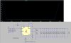
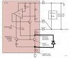
I am trying to figure out why I keep frying Linear Tech's LT1175. Datasheet here. I also attached an LTspice model as a representation of how I am using the part. The scope view is showing the Input and Output turned on and then turned off.

I am strapping this regulator as a -15v to -13.5v DC/DC. Over the past year this part intermittently fails(10% failure) and upon analysis I believe that it's a trace inside the part on the GND pin that is being compromised as when I ohm out a good part vs. a bad part that is the only difference I see between the two.

In the datasheet they talk about two ways you can hurt the chip. First is Output Voltage Reversal(page 13) which I have a diode to protect from the output being shorted to a positive supply(or backfed from a +supply). So, I don't think I'm hurting the chip in that way.

Second is the Input Voltage Lower Than Output. (Page 13) I assume that for the LT1175 they have a diode between the input/output. In my attached drawing, do I have the parasitic diode connected correctly? I'm trying to understand what they are warning about on this one. Anyone have ideas? Does it mean that when the output goes more negative than the input the parasitic diode will conduct and damage the part?

Any help would be much appreciated on this. Been spinning my wheels and hate to just blame the chip manufacturer as that is the easy way out. Also, if you have other ideas as to why I may be hurting this chip I'd like to hear it.

Thanks!
 

Attachments

  • LT1175.jpg
    LT1175.jpg
    126 KB · Views: 85
  • Parasitic.jpg
    Parasitic.jpg
    47 KB · Views: 85
parasitic diode seems right.

Datasheet is pretty clear:

"Reverse voltages between input and output above 1V will damage the regulator if large currents are allowed to flow. Simply disconnecting the input source with the output held up will not cause damage even though the input-to-outputvoltage will become slightly reversed"

It can't be heat or fake parts could it?

1Mohm seems really high for the feedback divider, but maybe it's fine.
 
Last edited:
"Reverse voltages between input and output above 1V will damagethe regulator if large currents are allowed to flow. Simply disconnecting the input source with the output held up will not cause damage even though the input-to-outputvoltage will become slightly reversed"

So, for sake of conversation, if you had -15v on the output and -10v on the input the part would fry? That's what they are saying here?


It can't be heat or fake parts could it?
Never had to deal with fake parts. Think it could be a cause? Thing is almost all the parts work at least once. Meaning, power is applied to the board, and they pass because output voltage is correct. Would a fake part work for a little bit and then just crap out? I guess it's possible. Do you know how I would investigate that?


1Mohm seems really high for the feedback divider, but maybe it's fine.

Where are you seeing the 1Mohm?
 
You protective diode would still destroy the LDO wouldn't it? Since even if the diode clamps the voltage at the output to ground when shorted to a positive supply, there's still 15V applied backward through the output to the input. It would be like a shorted load on the output condition with or without the diode, just.

Seems like you might be able to afford enough voltage headroom to use a series diode at the input instead.

So, for sake of conversation, if you had -15v on the output and -10v on the input the part would fry? That's what they are saying here?
IF ENOUGH CURRENT FLOWS, YES.


Never had to deal with fake parts. Think it could be a cause? Thing is almost all the parts work at least once. Meaning, power is applied to the board, and they pass because output voltage is correct. Would a fake part work for a little bit and then just crap out? I guess it's possible. Do you know how I would investigate that?
I HAVE NO EXPERIENCE WITH FAKE PARTS EITHER, BUT MAYBE OFFICIAL, REJECTED PARTS? WHO DO YOU ORDER FROM?


Where are you seeing the 1Mohm?
SUM OF FEEDBACK RESISTANCES

I like this datasheet note:
"Note to Reader:
To avoid confusion when working withnegative voltages (is –6V more or less than –5V?), I havedecided to treat the LT1175 as if it were a positive regulator and express all voltages as positive values, both in text and in formulas. If you do the same and simply add a negative
sign to the eventual answer, confusion should be avoided. Please don’t give me a hard time about “preciseness” or “correctness.” I have to fi eld phone calls from around the world and this is my way of dealing with a multitude of conventions. Thanks for your patience"
 
Last edited:
This particular part I buy from Arrow. Have they been known to somehow have "real failed parts" intermix into real parts that work correctly? ....that's scary..along with fake parts....sad really.
 
This particular part I buy from Arrow. Have they been known to somehow have "real failed parts" intermix into real parts that work correctly? ....that's scary..along with fake parts....sad really.
Arrow seems reputable so probably not that. Sometimes even the sellers are unaware though.

What about my diode comment? Have you tested the protection to see if it actually works?
 
Last edited:
What about my diode comment? Have you tested the protection to see if it actually works?

I haven't. Good point, I'll do that today to at least rule that out.

Kinda scratching my head on this one. Done a bunch of testing but adding more output capacitance while looking at input/output curves on scope and nothing seems to be obvious. I just hate saying that it's the part, but this is a vanilla design, not really doing anything out of the ordinary.
You could do destructive testing on some parts in different ways and see which one ohms out the same way. Or maybe you really do short the output to a positive rail 10% of the time:facepalm:

You said that it always runs at least once? Do the ones that fail fail immediately? Or only after running it a few times. I wonder...if you never actually see it fail mid-operation but only when you power it back up again, then maybe it has something to do with the shutdown.
 
The -13.5V is only supplying a few op-amps as the negative supply input so I'm doubtful that the opamps are shorting positive voltage...but weirder things have happened I suppose.

To be honest I don't have the data to know if it runs at least once. I may have misspoke there. But, I do know that it fails at all stages. So, the part is powered up, pasts tests but then further along the line it fails, from what it seems, totally random.
 
Status
Not open for further replies.

Latest threads

New Articles From Microcontroller Tips

Back
Top