Continue to Site

Welcome to our site!

Electro Tech is an online community (with over 170,000 members) who enjoy talking about and building electronic circuits, projects and gadgets. To participate you need to register. Registration is free. Click here to register now.

  • Welcome to our site! Electro Tech is an online community (with over 170,000 members) who enjoy talking about and building electronic circuits, projects and gadgets. To participate you need to register. Registration is free. Click here to register now.

Looking for an optical RPM Module

Status
Not open for further replies.

JulesP

Member
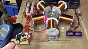
I have built a device that has a spinning rotor that I would like to display its rpm. I have been using a handheld laser device that bounces off a reflective strip on the rotor (see pic).

I’m looking for a permanent module attached to the base plate with a small display unit I can mount and with any electronics put on the PCB I’m preparing.

Magnetic options are complicated as the rotor has 5 magnets in it so an optical method is preferred.

Any ideas?

Thanks
 

Attachments

  • 4F498FA6-A7A4-468F-A351-8807E4E09495.jpeg
    4F498FA6-A7A4-468F-A351-8807E4E09495.jpeg
    536.3 KB · Views: 210
I know about these. They are all handheld devices which, as I described, is not what I’m looking for. I already have one.
 
Yes, saw it on the picture. Buy any on the link and disembowel for its circuitry if you want it attached permanently to your device.
 
Search "Digital tachometer module"

There are many variations of such as this available:
 
Thanks but none of those will work in my situation as they employ Hall sensors and as I have 5 magnets in my rotor I will get an rpm value 5 x what it should be- hence I said I needed an optical one.
 
The modules are the relevant part; they just have a logic / switch input - you can use any sensor type that is appropriate. Not all sellers provide sensors with the modules.

eg.
 
Last edited:
Have a look at HOA1405-2 .. .. .. .

It uses IR and would work in the same way as your handheld device.

MM
 

Attachments

  • HOA1405-2 Opto Interrupter.pdf
    287.6 KB · Views: 201
Well done for finding that. It’s much more like what I had in mind. So how do I interface that with one of those displays you referenced earlier? Does the meter have the important circuitry already inside and I just need to provide power to it? I’d rather not have to set up an Arduino microcontroller as well for it.

Thanks
 
Did you look at the document attached ?

It tells you that the device is simply an IR send & receive device; to display some results you would certainly need some sort of MCU. If you want all the work done for you I'd go with Externet's suggestion .. .. .

MM
 
Not yet.

Given my focus is on the PCB for the motor/generator I’m not too keen to build a tachometer from parts, either from a dismantled hand held device or discrete components, but will if I have to.

Do you think there is a meter that has an MCU already installed for use with a send and receive device? If so it may be in the industrial or automotive sector.
 
Do you think there is a meter that has an MCU already installed for use with a send and receive device?

I've never seen one, but then I haven't been looking .. .. .. I don't think you'll find an alternative to build your own, it is very straightforward.

MM
 
If you go self build then reconsider hall effect devices as you can easily do the division in software. A hall effect sensor, an Arduino nano and a display is probably all you need.

Mike.
 
Do you think there is a meter that has an MCU already installed for use with a send and receive device? If so it may be in the industrial or automotive sector.

The tach modules I posted earlier have the MCU etc., they just need a pulse signal at the "test" input pin, from any appropriate sensor or signal source.

That could come from the optical switch i posted, or the one MM posted.

The article I linked to give the setup for an optical sensor such as those to give a logic signal out - a couple of resistors.
 
If you go self build then reconsider hall effect devices as you can easily do the division in software. A hall effect sensor, an Arduino nano and a display is probably all you need.

Mike.
I already have a Hall sensor for my main FET trigger so I guess I can divert some of that signal to use for the rpm instead of installing a separate IR send receive device?
 
The tach modules I posted earlier have the MCU etc., they just need a pulse signal at the "test" input pin, from any appropriate sensor or signal source.

That could come from the optical switch i posted, or the one MM posted.

The article I linked to give the setup for an optical sensor such as those to give a logic signal out - a couple of resistors.
As indicated in my previous post I have a Hall sensor already so if I could use that then that would be a good input.

However my Hall sensor gives 5 pulses (via an inverting transistor) for every rev of my rotor (5 magnets inside) so can the tach modules let me set the ‘pulses/rev’ like the earlier article using an Arduino Nano?

There is no spec sheet for the Banggood one so if not then I imagine I could set up a divide by 5 circuit (4060 chip?) to produce just the one pulse/rev.
 
Last edited:
Here is my attempt at a 'divide by 5 circuit' based on information from the accredited source shown in the image. I have dropped the Hall probes 12V output to 5V for the flip-flops. With this I should be able to use my present Hall probe and a 'Bangood' meter.
 

Attachments

  • MOD 5 Circuit.jpeg
    MOD 5 Circuit.jpeg
    87.9 KB · Views: 189
Status
Not open for further replies.

Latest threads

New Articles From Microcontroller Tips

Back
Top