Continue to Site

Welcome to our site!

Electro Tech is an online community (with over 170,000 members) who enjoy talking about and building electronic circuits, projects and gadgets. To participate you need to register. Registration is free. Click here to register now.

  • Welcome to our site! Electro Tech is an online community (with over 170,000 members) who enjoy talking about and building electronic circuits, projects and gadgets. To participate you need to register. Registration is free. Click here to register now.

Looking for an optical RPM Module

Status
Not open for further replies.
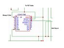
Instead of building a divide by five from individual logic parts, you could use a 74LS390.

This is a dual decade counter, but each decade is done as e divide by 2 and a divide by five.
So you just need to put the pulses in to one of the "B Clock" pins and pulses at one fifth of the frequency will come out of the corresponding "QD" pin.

JimB
 
That’s helpful, thanks. I assume I have to reduce the Hall probe 12V pulses to 5V first? My voltage divider values may be too high to give adequate current to this 74LS390 chip?

Perhaps instead I can use the CD4017BE decade counter as it can run on 12V supply? Otherwise I may have to reduce to 5V for a divider and then boost it again to 12V for the output to a meter. Not sure if this decade counter can be made to divide by 5.
 
Last edited:
Either should work.
I was thinking of a 74HC90; that has a /2 and a /5 section; the HC390 has two sets of /2 and /5; or a 4017 configured to divide by five is equally good.

The counter appears to be intended to be fed from a switch or open-collector signal, so just a FET or transistor switching to ground, controlled from the output of the counter, should give a count.
 
I was thinking of a 74HC90; that has a /2 and a /5 section; the HC390 has two sets of /2 and /5; or a 4017 configured to divide by five is equally good.

Do you have the full numbers for the 74HC90 and 390 as they are not coming up on Farnell. I take they can both be fed by a 12V supply and the FET Drain for the output is to give it enough power to drive the meter.
 
Do you need to sense the revolutions directly, or would it be OK to get that information from somewhere else?

Guessing from the picture, I expect that each of the coils are driven once for each rotation. If so, then you can just tap the voltage off of one of those coils to feed your counter.

No hall effect or optical sensor. And no division.
 
Do you need to sense the revolutions directly, or would it be OK to get that information from somewhere else?
I'm guessing there's some "slip" between the rotating magnetic field and the rotating drum. Hence measuring the drum speed will tell you how much slip.

Mike.
 
Nice idea but all the coils are in parallel and so are all fired simultaneously 5 times per revolution, that is each time one of the 5 rotor magnets passes the Hall sensor. If I used the FET firing pulses I’d still need to divide by 5.

I think the rpm meter modification will be straightforward now - inverted Hall pulse, CD4017 counting to 5, output to a FET base and Drain to rpm meter. The rotor is reaching 3,200rpm so approaching 270 BEMF pulses/sec at about 60V each are extracted from the main drive FET Drain. That should do nicely.

Thanks to all for the suggestions.
 

Attachments

  • Hall Sensor 'On' Angle 3.jpeg
    Hall Sensor 'On' Angle 3.jpeg
    87 KB · Views: 175
Last edited:
I'm going with the CD4017 as I found one in my box of bits but I have a query on its connections, as shown in the attached pic showing part of my schematic for the PCB. Pin 1 is the Binary 5 pin which is connected to RESET and will go to my FET Gate. The Hall signal comes into CLOCK (14) so can I leave Pin 12 (COUT) unconnected?
 

Attachments

  • CD4017BE Connections.jpeg
    CD4017BE Connections.jpeg
    103.3 KB · Views: 160
I'd take the FET gate signal from a lower output, eg. Q2 or Q4; they will stay high for a full input cycle so give a consistent pulse to the tacho module,

The Q5 output will only give a very short spike, just the time it takes for the reset to propagate through the IC.
 
I'd take the FET gate signal from a lower output, eg. Q2 or Q4; they will stay high for a full input cycle so give a consistent pulse to the tacho module,

The Q5 output will only give a very short spike, just the time it takes for the reset to propagate through the IC.
I see your logic but surely, as the unit counts from 0 to 10 each Q output will change from low to high and back again as the value increments? I.e. none of the Q outputs will remain high throughout the count to 5? What am I missing here?
 
Last edited:
From the way I understand it your existing circuit requires a direct input from the hall sensor. It is only the tachometer that requires the number of pulses from the hall sensor divided by 5.
This is how the 4017 counts.

Initial reset state. state 0 Q 0 high for the period between hall sensor pulses.
state 1 Q 1 high for the period between hall sensor pulses.
state 2 Q 2 high for the period between hall sensor pulses.
state 3 Q 3 high for the period between hall sensor pulses.
state 4 Q 4 high for the period between hall sensor pulses.
state 5 Q 5 goes high but that causes count to be reset back to zero. This will only take a few microseconds so it will only be in that state for that amount of time.

Note I hit a key that took me out of typing before I had finished so I had to use the edit function to complete my post.

Les.
 
Last edited:
Each output will stay high for one input clock period, so at 270Hz almost four mS
- except the one output connected back to reset.

That will reset itself as soon as it activates, so the pulse from that will be something like 100 - 300nS, depending on the individual IC and operating voltage.
 
Ok got you. As per graph here.
 

Attachments

  • EC2A9E77-2467-4A52-99A2-B7CCC9433E7C.jpeg
    EC2A9E77-2467-4A52-99A2-B7CCC9433E7C.jpeg
    58.8 KB · Views: 174
From the way I understand it your existing circuit requires a direct input from the hall sensor. It is only the tachometer that requires the number of pulses from the hall sensor divided by 5.
This is how the 4017 counts
If I get 5 Hall pulses per rev then that would give an rpm reading 5x the real reading. So I need to divide Hall pulses by 5.
 
That's the normal count timing; I cannot find an image showing the a count with "self reset" timing - but from the data sheet, it will change to output state zero within a fraction of a microsecond, once the pin connected to reset goes high.
 
That’s sounds right. I will use say Q4 for my gate connection. Do I need to have pin 13 (enable) grounded or left NC?
 
Grounded - never leave a normal CMOS input (or just about any general IC input) floating, it can cause unpredictable behaviour or even damage.
 
Ok, thanks. When I’ve built the PCB and got it all running again with the upgrades I can put up a link to a video of it. Some might be interested.
 
Status
Not open for further replies.

Latest threads

Back
Top