Continue to Site

Welcome to our site!

Electro Tech is an online community (with over 170,000 members) who enjoy talking about and building electronic circuits, projects and gadgets. To participate you need to register. Registration is free. Click here to register now.

  • Welcome to our site! Electro Tech is an online community (with over 170,000 members) who enjoy talking about and building electronic circuits, projects and gadgets. To participate you need to register. Registration is free. Click here to register now.

Long delay affected by low temperature?

Status
Not open for further replies.

AGCB

Member
I'm trying to replace the crude control in a animal feeder with a PIC.
Turn on a motor through current amplifier for 3 seconds then wait 24 hours and do it again. It works great on my table at room temperature (within a few seconds in 24 hours) but when it gets outside in 30F it fails. I'm using a 12F675 with 4 Mhz external oscillator.

Should temperature affect oscillator timing or anything else?
Partial code attached
Thanks
Aaron
 

Attachments

  • feeder code.txt
    1.4 KB · Views: 169
When you say "it fails", what do you mean? It doesn't work at all, it runs at half speed? Double speed?

Mike.
Edit, can you post a schematic?
 
Mike
Tried to send file but too big.
It's just the PIC output through a NPN/IRF9540 MOSFET amp. Worked when 1st put it outside but after it cooled off, no. I don't know if it goes too late or too soon or not at all.
 
Last edited:
I was just out there and it had tripped after the animals were gone. So later than supposed to.
 
So what kind of accuracy should be expected with this PIC and external oscillator (can type) given the ambient temperature of 15 - 40 degrees F
 
Have you considered the glitch you may get from the motor? Hence, why I asked for a schematic so we actually know what we're talking about.

BTW, you still haven't told us how it fails.

Mike.
 
We need to know more about your circuit.
external oscillator (can type)
Is it a two legged part like this: (where you use two pins on the micro and have two capacitors)
1574521485183.png

or more like this: (where you use only one pin on the micro)
1574521511868.png

We need to know more about the code.
Turn on a motor through current amplifier for 3 seconds then wait 24 hours and do it again.
So right after reset it runs the motor. So if the power gets interrupted the motor runs. If the part reset for some reason it runs the motor.

Normally the crystal is very good on timing. I think you have oscillator problems or more likely you have a reset problem.
 
what is the power supply?
got any input/output devices, ? such as a LEd indicator and a button, could maybe add code to set the led on at boot up and then the button to turn it off, so if we go back out and led is on you we there was brownout or some other form of reset
 
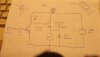
Here's the output circuit from the PIC. The MOSFET is plenty good for the small 6 volt motor. All is powered by a 6 volt SLA gel battery. The PIC circuit is simple as can be and uses the sqaure 1/2 can, 4 pin oscillator. I've also attached the complete code but it may be full of my own notes and reminders. The motor runs right away when powered up or reset then supposed to repeat after 24 hours. Inside on my work bench I tested 3 days and it was accurate to within a few seconds. It had been outside last week and acted the same way. I took it inside to check everything and was good so tested 3 days, flawless but when it gets out in the cold the long delay gets longer.
;============================================================================= ; TITLE BLOCK ; Project Name...TestFeeder (12F629) Date...11/15/2011 ;This project is...Test program. Turns on GPIO,1 for 3 secons then off for 24 hours ;Lessons Learned.. internal oscilator is not very acurate! 4Mhz can oscilator was installed to get seconds/day accuracy ;This was originaly written for 12F629 but converted (in program) to 12F675 by changing list and #include ;============================================================ ;Instuctions 1...save file as .asm in c:/d&s/T/my docs/A/pic ; 2...PROJECTS>ADD FILES TO PROJECT ; 3...PROJECT>BUILD OPTIONS>PROJECT MPASM TAB Disable ; case sensitivity ;============================================================ list p=12F675 ;select device in configuration tab #include <p12F675.inc> radix hex __config _XT_OSC & _WDTE_OFF & _PWRTE_ON & _MCLRE_ON & _BODEN_OFF & _CP_OFF & _CPD_OFF ;----------------------------------------------- ; Pin assignments: EQU ;gpIO,1 is output to motor circuit ;----------------------------------------------- ; Constants: EQU ;------------------- VARIABLE DEFINITIONS------------------------ cblock 0x20 endc ;=========================================================== org 0x00 goto start ; org 0x04 ;DELETE IF NO ISERV (with ;) ; goto iserv ;======================================================================== ; Here is where to put CONDITIONAL ASSEMBLY instructions ; i.e. #define NAME ; at the code location ifdef debug ; ##### ; else ; use {;} to include or not ##### ; endif ;#define debug ;add or remove parenthesis from this line ;=========================================================== ; Initialisation no ANSEL on 12F629 because no A-D Start banksel GPIO clrf GPIO ;init gpio all outputs banksel osccal movlw b'10000000' movwf osccal ;center oscillator frequency banksel cmcon movlw b'00000111' ;comparators off if not needed movwf cmcon ; or configure comparators if using banksel trisio clrf trisio ;gpio all outputs banksel gpio clrf gpio ;all outputs low ;================ Main loop================================== ;calibrate oscilator if using internal ;bsf status,rp0 ;call 3ffh ;movwf osccal ;bcf status,rp0 ;main loop again bsf gpio,1 call Delay3Secs bcf gpio,1 call Delay24Hours goto again ;continue forever ;=================Sub routines here========================= ;=================DELAYS here=============================== ; DO NOT allow interrupts while in timing loops ; bcf intcon,gie ;disable interrupts ; bsf intcon,gie ;enable interrupts Delay3Secs ; Delay = 3 seconds ; Clock frequency = 4 MHz ; Actual delay = 3 seconds = 3000000 cycles ; Error = 0 % cblock d1 d2 d3 endc Delay ;2999995 cycles movlw 0x1A movwf d1 movlw 0x8B movwf d2 movlw 0x07 movwf d3 Delay_0 decfsz d1, f goto $+2 decfsz d2, f goto $+2 decfsz d3, f goto Delay_0 ;1 cycle nop ;4 cycles (including call) return Delay24Hours ; Delay = 86397 seconds ; Clock frequency = 4 MHz ; Actual delay = 86397 seconds = 86397000000 cycles ; Error = 0 % cblock c1 c2 c3 c4 c1_4 endc Delayc ;86396999995 cycles movlw 0xD6 movwf c1 movlw 0xB1 movwf c2 movlw 0x27 movwf c3 movlw 0xD5 movwf c4 movlw 0x02 movwf c1_4 Delay_0c decfsz c1, f goto $+2 decfsz c2, f goto $+2 decfsz c3, f goto $+2 decfsz c4, f goto $+2 decfsz c1_4, f goto Delay_0c ;1 cycle nop ;4 cycles (including call) return ;=================ISERV here================================ ;------------SAVING context, W AND PCLATH REGISTERS cblock w_temp status_temp pclath_temp endc MOVWF W_TEMP ;Copy W to TEMP register SWAPF STATUS, W ;Swap status to be saved into W CLRF STATUS ;bank 0, regardless of current bank, Clears IRP,RP1,RP0 MOVWF STATUS_TEMP ;Save status to bank zero STATUS_TEMP register MOVF PCLATH, W ;Only required if using page 1 MOVWF PCLATH_TEMP ;Save PCLATH into W CLRF PCLATH ;Page zero, regardless of current page iserv ;(Insert user code here ) ;-------------Restore context-- MOVF PCLATH_TEMP, W ;Restore PCLATH MOVWF PCLATH ;Move W into PCLATH SWAPF STATUS_TEMP, W ;Swap STATUS_TEMP register into W MOVWF STATUS ;Move W into STATUS register SWAPF W_TEMP, F ;Swap W_TEMP SWAPF W_TEMP, W ;Swap W_TEMP into W retfie END

Thanks for trying to help.
Aaron
 

Attachments

  • E-mail DSCF4180.jpg
    E-mail DSCF4180.jpg
    35.3 KB · Views: 170
How are going from 6V battery to 3.3V for the micro? or 5V?
Regulator and what capacitors?
What are you doing with the reset pin?
 
I'm dropping the 6 volt with 2 diodes in series. Have 10 and .1 uF capacitors across Vdd/Vss. MCLR pulled up with series 100 and 10k resistor with reset switch to ground between resistors
 
Can you post a complete schematic that's bigger than a postage stamp - including ALL components. What you posted above is unreadable.

Mike.
but when it gets out in the cold the long delay gets longer
How much longer?
 
Just to throw my two cents in.....

Take a look here https://www.electronics-notes.com/a...ature-compensated-crystal-xtal-oscillator.php. Do some math and see what the effect of -40 ppm is on your oscillator - would that account for the discrepency? If that could account for the problem, and you are sure that is the problem (I know there can be other reasons), you can change oscillators.

Not saying you want to get a tcxo, but this is a good read - Are not crystals sold with different temperature/stability characteristics?

In any event, for what you want to do , I think you may get much better results using timer1 and an external 32768Hz crystal. I think there is probably a lot out there on this - no?
 
A 50 ppm crystal can have an error of ±1500 seconds per year.
Edit, sorry, me being an idiot and reading 24h as 1 year!

Mike.
 
Last edited:
Could high humidity (condensation) be a contributing factor?
 
It could be several factors. Quality of crystal may be one issue. Try HS_ oscillator selection instead of XT_
Your power supply is not the best, but the PIC should run down in the 4.0V range with no issues. But, since you are running the motor and PIC off the same battery, a voltage sag or spike could be an issue. When the motor is colder, it will draw more current, causing a larger voltage drop when it starts.
Add a 1000pf cap across the Vdd/Vss legs
A better schematic with the PIC wiring shown would help.
Such a temperature change would not affect the PIC oscillator by much more than 1% or so (maybe 2%?). Do you have the 15-30pf caps on the crystal legs (to ground)? Those are usually required for stable oscillation.
 
Could high humidity (condensation) be a contributing factor?
There could be lots of reasons which is why I asked for a complete schematic - but the outside conditions would be helpful too. Reading between the lines it sounds like proper decoupling capacitors are missing. Couldn't see from the diagram above if the mosfet is N or P and how it's being turned on etc.

Mike.
 
He states he is using the "IR9540 ", I think he means the IRF9540. That said, full on requires -10V Vgs, which cannot be supplied via a 6V power supply. He may be better off finding some different "logic level" P channel MOSFET instead. While it may work with the setup he has now, the MOSFET may not be fully on.
Also, why high side switching? Maybe that is the way it was in other schematic, but using a IRL type (like IRL540) N channel MOSFET on the low side for switching should also work, provided the high/low logic is checked for proper levels. This would allow direct gate control from the PIC without the need for an intermediate transistor.

SO, most of us agree, we need a full schematic, including crystal capacitors, bypass caps, etc.
 
Try HS_ oscillator selection instead of XT_
sqaure 1/2 can, 4 pin oscillator
Looks like no internal osc being used.

The problem could be in this line: ( I don't know enough to say)
__config _XT_OSC & _WDTE_OFF & _PWRTE_ON & _MCLRE_ON & _BODEN_OFF & _CP_OFF & _CPD_OFF

I still think it is a reset problem not a osc problem. Maybe reset=power.
 
Status
Not open for further replies.

Latest threads

New Articles From Microcontroller Tips

Back
Top