Continue to Site

Welcome to our site!

Electro Tech is an online community (with over 170,000 members) who enjoy talking about and building electronic circuits, projects and gadgets. To participate you need to register. Registration is free. Click here to register now.

  • Welcome to our site! Electro Tech is an online community (with over 170,000 members) who enjoy talking about and building electronic circuits, projects and gadgets. To participate you need to register. Registration is free. Click here to register now.

Logic level shifter with BSS138 on an SPI bus

Status
Not open for further replies.

earckens

Member
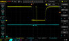
In the schematic below I use a classical setup for a logic level shifter. However, in this case, when using this for an SPI bus MISO signal the mosfet refuses to switch its drain to low. Attached scope output: yellow is MISO low level, blue is MISO high level.

Board track lengths for this circuit are less than 1cm.

Vcc in my case is 3.3V so a level shifter is not technically required but the issue is that the high level MISO can change -project dependent- from 3.3V to 5V. In the case of Vcc being 3.3V (as is in my current case) then also the resistor values R2, R4, R6 and R10 need to be 0 Ohm.

For this specific mosfet level shifter it does not matter if the high level voltage is equal to the low level voltage since it is the difference between gate and source voltage that decides whether the mosfet switches on or not (the gate-source threshold voltage is 1.5V max per the datasheet).

Switching on however does not occur, even after:
1. changing the mosfet to another BSS138
2. changing R8 from 10k to 1k
3. verifying this board for manufacturing defects
4. reducing the SPI bus speed from default 8MHz to 1MHz

The circuit does work when I short drain and source. But obviously that defeats the purpose.

What should I be looking at to solve this case?
 

Attachments

  • LoRa_module_narrow_v2.pdf
    40.5 KB · Views: 228
  • DS1Z_QuickPrint17.jpg
    DS1Z_QuickPrint17.jpg
    79.8 KB · Views: 211
Last edited:
The only thing I can think of, as you have checked for a dead FET etc., is a mixup in the FET pinout, such as source and gate swapped?
 
The only thing I can think of, as you have checked for a dead FET etc., is a mixup in the FET pinout, such as source and gate swapped?
And the really strange thing is: this circuit does work in a previous version of this board: see attachment.

Here a jumper connects 3.3V with Vcc, the LM1117, C1, C2 are not installed since this too worked with Vcc being 3.3V
 

Attachments

  • LoRa_module_narrow_v1.pdf
    39.1 KB · Views: 212
have you tested it on multiple PCBs, or just one?
We have had boards with odd copper faults before now, even a couple of "bare board tested" ones that had traces of swarf in the solder resist causing erratic problems.
 
have you tested it on multiple PCBs, or just one?
We have had boards with odd copper faults before now, even a couple of "bare board tested" ones that had traces of swarf in the solder resist causing erratic problems.
Not yet, I will do.

I did check the tracks under microscope (double sided board), total length about 3cm so doable to verify; indeed in the past I had a delivery with erratic manufacturing errors on one design.
 
That too was checked and is ok: the Eagle BSS138 package corresponds with the BSS138 datasheet.

If you've got one of the cheap Chinese (Atmel based) component testers (and everyone should :D) try checking the BSS138, the component tester will not only tell you it's basic specifications (and if it's working OK), but will tell you which pin is which. Not all devices have the same pinout, often different manufacturers use different pins - been there, been caught!.
 
If you've got one of the cheap Chinese (Atmel based) component testers (and everyone should :D) try checking the BSS138, the component tester will not only tell you it's basic specifications (and if it's working OK), but will tell you which pin is which. Not all devices have the same pinout, often different manufacturers use different pins - been there, been caught!.
Hi, can you give me a reference for this tester please?
 
There are a good number of slightly different models available, but all are based on the original design - just with extras added - some are text displays, some are graphic displays. They are quite fun to build, I've made about 5 different ones :D

The one I use at work is a two line text display one.

It gets used most for confirming resistor values, with the stupid confusing colours on 1% and 0.5% resistors :D
 
I took one of these SOT23 BSS138, soldered wires to the 3 pins and tested with 3.3V between G and S.

Between D and S with 0V on G: infinite MOhm; with 3.3V between G and S: 136MOhm between D and S.
 
After testing several BSS138: not one worked.
Installed a AO3400 (actually not suitable because of much higher stray capacitance): all worked.

BSS138: defective batch.
 
(Transistor tester photos )

There are a good number of slightly different models available, but all are based on the original design - just with extras added - some are text displays, some are graphic displays.

Off topic, but I bought one of these off ebay after seeing them mentioned in this thread; just received it today.
It's a graphical version with a flat pack clear case - and it is a very impressive little gadget!

Thanks MacIntoshCZ & Nigel for mentioning them & providing the extra info.
 
Off topic, but I bought one of these off ebay after seeing them mentioned in this thread; just received it today.
It's a graphical version with a flat pack clear case - and it is a very impressive little gadget!

Pretty cool aren't they :D

If you google you can find the original details for them, which explains how they work, and all the different tests they do (from the original model).
 
Status
Not open for further replies.

Latest threads

New Articles From Microcontroller Tips

Back
Top