Continue to Site

Welcome to our site!

Electro Tech is an online community (with over 170,000 members) who enjoy talking about and building electronic circuits, projects and gadgets. To participate you need to register. Registration is free. Click here to register now.

  • Welcome to our site! Electro Tech is an online community (with over 170,000 members) who enjoy talking about and building electronic circuits, projects and gadgets. To participate you need to register. Registration is free. Click here to register now.

Logic gate HIGH/LOW to enable/disable BLDC controller

Status
Not open for further replies.

BikerMark

New Member
Hi,

Just signed up and happy to be eligable to post a question here.
Somebody please look into my solution for this problem:
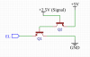
I have exchanged the controller in my (45 km/h) Ebike. I want it to disable the BLDCmotor when the brakes are hit. Hitting the brakes is signalled by a GND-connection on the signal wire. This causes the brake-light to glow up as well.
The controller has an enable/disable port (EL). If HIGH, controller works, LOW disables it.
If I connect brakes signal to EL, brake lights are continously ON. Not good.
How to have EL HIGH when riding, and LOW when braking? My idea was this:

120607


I'm wondering whether this is a good solution, is it possible in the first place, does it need some adjustment or some pull-up or -down resistors?

Any thoughts or help are highly appreciated!

TIA,
Mark
 

Attachments

  • 1568897528259.png
    1568897528259.png
    21 KB · Views: 189
How much current is need? If not much why not use a logic gate, a not or inverter, they are the same thing. Or make one as shown here; **broken link removed**
 
Not much current is needed; it's just a signal.
The logic gate is what came across my mind (it's similar to the if()statement in code) but I'm not experienced enough to embed this into a piece of electronic circuitry.
The schematic shown is my guess for something like:
Code:
if(signal == HIGH){
  digitalWrite(EL,HIGH);
  } else if(signal == LOW){
    digitalWrite(EL,LOW);
    }
 
And I'm not code savvy. Why would you put a micr into the system when a few components shown in the link or a single logic gate would do what you want?
 
A simple diode and resistor may be all you need.

Connect the anode of the diode to the EL signal and the cathode (banded end) to the brake light wire.
If the EL signal does not stay high (on) when the brakes are off, add eg. a 1K resistor between EL and +5V

The diode allows the brake switch to pull the EL signal low, but not vice-versa so the brake light should not be affected.

Use eg. a 1N4000 series diode, 1N4002, 4004, 4007 etc.
 
Shortbus, with some more experience I might be able to answer your question on why not to use a few components to do what I want. I'm still discovering this field... and learning by trial and error.

Thank you rjenkingsgb for your answer.
Maybe I was overcomplicating the thing. Basically, I need connection between GND and EL if Signal is LOW.
Further research now brings me to an enhanced-type MOSFET:
120639

Besides, I noticed that EL was carrying +5V by default. I connected it to GND without any resistor (in line with the description of the controller), which did not cause any short circuit.

Would this schematic work, according to you guys? It seems to me the way to go.
 
A word of caution. Some BLDC controllers will go into "brake mode" when disabled and could cause excessive braking. Test at low speed first. The mosfet will not be fully turned on by the 2.5v gate voltage. Try a PNP transistor with a suitable base resistor.

Mike.
Edit, where is the 2.5V coming from? If it's the led then it could be a problem.
 
Basically, I need connection between GND and EL if Signal is LOW.

That is exactly what a simple diode will do! They conduct one way only.

The FET will switch the signal but also invert it - it turns on when the gate is sufficiently positive (depending on the type of FET) and then the "EL" would in effect be shorted to ground.

That's the reverse of what you need, from your earlier description.

Also, you need additional resistors to protect the gate from excess voltage.
 
Thnx for alerting, Mike. It appears however the controller turns into a total passive state when EL is 0V.

rjenkinsgb; I just tried a 4007 between brakelight and EL with no avail. Perhaps because EL carries 5V (as a result of an internal pull-up in the controller?)
The EL shorted to ground is exactly what I need indeed, but then in the case of a LOW signal at Gate. I'm still somewhat confused on PNP and NPN and enhanced FETs and transistors.
I'm about to try and error a bunch of transistors now...
 
The input needs to be low (to disable it) when the brake signal is high (brake on) so an inverter is required. In you circuit above replace the mosfet with something like a 2N2222 or 2N3906 with a 1800Ω (1k8) resistor in the base line and see how that goes. Are you able to measure the current between EL and Ground in case it's not a simple pullup?

Mike.
 
Shortbus, with some more experience I might be able to answer your question on why not to use a few components to do what I want. I'm still discovering this field... and learning by trial and error.

Thank you rjenkingsgb for your answer.
Maybe I was overcomplicating the thing. Basically, I need connection between GND and EL if Signal is LOW.
Further research now brings me to an enhanced-type MOSFET:
View attachment 120639
Besides, I noticed that EL was carrying +5V by default. I connected it to GND without any resistor (in line with the description of the controller), which did not cause any short circuit.

Would this schematic work, according to you guys? It seems to me the way to go.

That is the same basic thing that was in my earlier link -
120659


What you show should be a N mosfet not a P mosfet.
 
The brake signal is supposedly LOW when the brakes are on?
Indeed; when I measure voltage it is:
while active (LED is continiuously ON, this is the signal which is forked): 2.45V
while braking: (Led still ON, and enhanced by braking Light): 0.00V (maybe 0.01V, in fact LOW)

Which way around did you connect the diode?
Eventually I connected it both ways, initially conforming your suggestion. Neither worked.

Just returned from local components shop with a bunch of 2N2222, a switching relay and some optocouplers. Hope that will do :D
 
Last edited:
Assumptions: 2.5V signal is 0V/2.5V, Relay has a 5 volt coil,
Assumptions seem to be allright.
Moving the 2N2222A after the coil: I can sort of understand why.

What puzzles me is the diode (1N4148). What is it doing, why is it there?
I hope you can clearify, so I can learn.

TIA!
 
Assumptions seem to be allright.
Moving the 2N2222A after the coil: I can sort of understand why.

What puzzles me is the diode (1N4148). What is it doing, why is it there?
I hope you can clearify, so I can learn.

It's to prevent the back EMF from the relay coil blowing the transistor - it's an absolutely essential part, and a VERY basic circuit - you should never see a relay fed from a transistor without one (although it may be hidden where you can't see it - I bought some DIL reed relays recently, they have the diode built inside).
 
Thank you, guys, really appreciate your help! I think I'm progressing slowly...
I'm designing a PCB right now, based on the schematic of ronsimpson.
If you like, you can view, review or even contribute: here.
120665
 
Status
Not open for further replies.

Latest threads

New Articles From Microcontroller Tips

Back
Top