Continue to Site

Welcome to our site!

Electro Tech is an online community (with over 170,000 members) who enjoy talking about and building electronic circuits, projects and gadgets. To participate you need to register. Registration is free. Click here to register now.

  • Welcome to our site! Electro Tech is an online community (with over 170,000 members) who enjoy talking about and building electronic circuits, projects and gadgets. To participate you need to register. Registration is free. Click here to register now.

LM723 based PSU with min voltage of 0,00V

Status
Not open for further replies.

earckens

Member
Last October I contacted this forum after having decided to reconstruct my functioning student-era LM723-based PSU. The most interesting part about this particular PSU was that it had a fairly ingenious (not invented by me :cool:) way to have a minimum voltage of 0,00V. For the rest it used adjustable current limiting up to 3A and max output of about 30V. The transformer was an oldfashioned rectangular iron core of about 90VA and two secondary 12V coils, at full current it's maximum voltage dropped.
New specs I set forward for a upgraded PSU:
0,00V minimum output
>40V max output
3A max current
I had recently bought a toroidal 150VA transformer (2x 15V 5A), all other parts had to be re-used.
On this forum I started a thread (https://www.electro-tech-online.com/threads/lm723-psu-with-0v-lowest-voltage.148899/) where, in order of appearance, I received help from Nigel Goodwin, spec, dr pepper, Les Jones and a few others. By far the most prolific contributor had been spec, to whom my warmest gratitudes, and of course to all others too.
Purpose was to re-use as much as possible from the original design ideas yet increase both current and voltage capabilities, as well as introduce a current limiting warning LED.
Another target was to introduce a microcontroller for display and warning purposes.

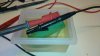
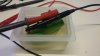
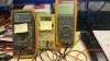
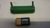
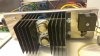
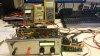
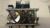
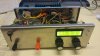
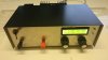
Today, after months of on and off time devoted to this project, I did final "burn-in" tests, you can see on the pictures what I used as a load (because of the dissipation of max +90W I used watercooling :D). Voltage stays perfectly stable, the transformer does not give a "crimp", current limiting goes perfect at work at 3.2A, and current limiting is adjustable too; no molten or burnt components during tests..

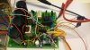
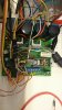
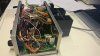
On the picture of the pcb (see below) to the right is a socket that is reserved for a Atmega168P controller: display of V and I (current measured with INA219 I2C module) and transformer and heatsink temperature sensors (LM35), as well as supervision of temperatures and generation of the necessary alarms. The controller (not yet installed at time of picturetaking) is meanwhile installed and all performs well, I just need to do voltage and temperature calibrations.

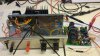
Included too is the final schematic drawing (thank you to spec who introduced me to CAD with Eagle).

C++ program files and microcontroller hardware layout available on demand. These are not included in this schematic for readability purposes.

Erik
LM723-labPSU-0V-46V-v2a.png
 

Attachments

  • DSC_0766.JPG
    DSC_0766.JPG
    909.2 KB · Views: 735
  • DSC_0767.JPG
    DSC_0767.JPG
    897.7 KB · Views: 499
  • DSC_0768.JPG
    DSC_0768.JPG
    1 MB · Views: 565
  • DSC_0769.JPG
    DSC_0769.JPG
    1.1 MB · Views: 586
  • DSC_0770.JPG
    DSC_0770.JPG
    1.2 MB · Views: 514
  • DSC_0771.JPG
    DSC_0771.JPG
    719.7 KB · Views: 553
  • DSC_0772.JPG
    DSC_0772.JPG
    1.1 MB · Views: 1,064
Nice work Earckens,

Your perseverance has payed off.:cool:

spec
..and the very helpfull support I received here!!

Now running with controller installed (and calibrated): see pictures
 

Attachments

  • DSC_0773.JPG
    DSC_0773.JPG
    976.4 KB · Views: 409
  • DSC_0774.JPG
    DSC_0774.JPG
    1.3 MB · Views: 470
Last edited:
The 723 is, like the 555, one of those ancient devices which simply refuses to go away.

The reason being that one can make them do a myriad things that were never envisioned by their original designers, thanks to a simple and straightforward architecture.
All it takes is a little study of the IC innards and some analog design knowledge.
That and the willingness to perform some calculations, and presto! you have a nice circuit like what you are showing here.

All that you require now, is to dress up the wires and anodize the case and you'll have an awesome project to show off.

Congratulations.
 
All that you require now, is to (..) anodize the case and you'll have an awesome project to show off.

Congratulations.

Anodizing: I had not thought of that: how is that done?

Thank you for the compliments! But they also go for all those who helped me here on this forum. Without your help I would not have been able to do this. What a fantastic community!
 
Last edited:
Excellent.
There are 2 of these now, mine is very similar, for obvious reasons.
I spent some time improving the current limit function as the built in limit in the '723 is a bit noisy.
So briefly whats the purpose of the lm393, looks like a current limit indicator.
Also mine displays wattage, its simple to do in code and I find it usefull, for rating power supplies and getting an idea of heatsinks for circuits under test.
I sometimes leave min on charging batteries and things, so I've thought about revisiting and getting the uC to shut down the '723 on a transformer or heatsink overtemp, just for safety.
 
Here is an upgrade to the schematic (thank you spec!!): added output protection diodes D1 and D2.

Also make sure the heatsink on Q6 is big enough, temperature can climb on that darlington (on the picture it is the one with the black heatsink inside the case now). Before the change it went to +95C, currently it stays at 62C without cover.

The LM393 is a current limit indicator, with thanks to spec!

Cleaning up the wiring? I make sure they don't touch heatsinks but I leave the rest as is, it is already a major undertaking getting the pcb in and out without all wires strapped and bundled.

To dr pepper: shutting down the LM723 is doable but to restart it would you use a reset button or let the software take care?

... so I've thought about revisiting and getting the uC to shut down the '723 on a transformer or heatsink overtemp, just for safety.

LM723-labPSU-0V-46V-v3.png
 

Attachments

  • DSC_0775.JPG
    DSC_0775.JPG
    1.1 MB · Views: 395
  • DSC_0776.JPG
    DSC_0776.JPG
    1 MB · Views: 448
  • DSC_0778.JPG
    DSC_0778.JPG
    1 MB · Views: 385
  • lab PSU LM723 v3.pdf
    24.5 KB · Views: 413
  • DSC_0779.JPG
    DSC_0779.JPG
    953.5 KB · Views: 654
Last edited:
I don't get it.

For my 0.00 volt power supply I just short the two power leads together. :rolleyes:

I'm not sure what the current limit is at 0.00 volts but when I hooked up my pair of 600 amp continuous duty rated three phase Miller welding power supplies to my 0.00 volt power supply in parallel and turned them up all the way it had to be approaching near infinity being they normally will pull something like 35 KW each on 480 VAC three phase when shorted out. :eek:
 
...but when I hooked up my pair of 600 amp continuous duty rated three phase Miller welding power supplies to my 0.00 volt power supply in parallel and turned them up all the way it had to be approaching near infinity being they normally will pull something like 35 KW each on 480 VAC three phase when shorted out. :eek:

If I were you I would try and connect your rig to your car battery :D
 
If I were you I would try and connect your rig to your car battery :D

But my car battery is a 12 volt DC source not a 0.00 volt AC source. (That should be painfully obvious.) :rolleyes:
 
Looks ok.
Does the current limit led come on at the precise point of current limit?, I went a bit ott on my design, in the end I just put an led in series with the input to the current limit integrator which deliberately had a low i/p impedance so the led had to be on as current limit came in effect.
An alternative for D2 would be to put the diode anode to the + o/p terminal and cathode to the collectors of the o/p transistors (and put a link where the diode was) you'd still have some protection for the o/p devices, instead of opening the circuit to reverse voltages to the supply you'd charge up the resovoir caps to the backfed voltage, or in the case of a 'spike' short it into the caps, I've seen this on commercial stuff, but theres nowt wrong with how you have it, except maybe d1 might be better a uf4002 or something, if you had an inductive load pulling max current and you unclipped one of the leads you might frazzle a little '4148.
 
Last edited:
Looks ok.
Does the current limit led come on at the precise point of current limit?, I went a bit ott on my design, in the end I just put an led in series with the input to the current limit integrator which deliberately had a low i/p impedance so the led had to be on as current limit came in effect.
An alternative for D2 would be to put the diode anode to the + o/p terminal and cathode to the collectors of the o/p transistors (and put a link where the diode was) you'd still have some protection for the o/p devices, instead of opening the circuit to reverse voltages to the supply you'd charge up the resovoir caps to the backfed voltage, or in the case of a 'spike' short it into the caps, I've seen this on commercial stuff, but theres nowt wrong with how you have it, except maybe d1 might be better a uf4002 or something, if you had an inductive load pulling max current and you unclipped one of the leads you might frazzle a little '4148.
Hi dr pepper,

the LM393 starts the LED low as soon as any current limit comes into play, and as soon as the full current limit works (voltage to zero) the LED is at full brightness. No lead or lag.
 
Looks ok.
Does the current limit led come on at the precise point of current limit?, I went a bit ott on my design, in the end I just put an led in series with the input to the current limit integrator which deliberately had a low i/p impedance so the led had to be on as current limit came in effect.
An alternative for D2 would be to put the diode anode to the + o/p terminal and cathode to the collectors of the o/p transistors (and put a link where the diode was) you'd still have some protection for the o/p devices, instead of opening the circuit to reverse voltages to the supply you'd charge up the resovoir caps to the backfed voltage, or in the case of a 'spike' short it into the caps, I've seen this on commercial stuff, but theres nowt wrong with how you have it, except maybe d1 might be better a uf4002 or something, if you had an inductive load pulling max current and you unclipped one of the leads you might frazzle a little '4148.
Very usefull, thks!
However the reason for this instead of your proposal is because when I did the latter I could not get 0,00V at the output.
 
I don't get it.

For my 0.00 volt power supply I just short the two power leads together. :rolleyes:
When you say it quickly, a 0.00v power supply does not really make much sense.
However, from my own personal experience I have quite often needed a voltage source which can be adjusted all the way down to zero volts.
Not necessarily for providing power to something, but for providing a signal or indication, such as when testing a meter.
Admittedly you don't need much current when testing most meters, so something like a 20Amp psu which can adjust to zero volts could be a bit of overkill. But a 1 or 2 amp PSU for general purpose bench use, if often more useful if it will adjust to 0.00 volts.
Just my opinion.

JimB

Oh I know. I've done the same. The thing is anyone who designs a signal/power source around a basic common dual rail power source can make a very stable and reliable, and even fairly high powered, source with 0.00 volt output capability with minimal components.

I just found the excitement over having made a circuit that could put out no power or signal of any kind rather amusing. :D
 
Hi Earcknes,

D1, 1N4148, cathode, should be connected to the junction R23/R29 rather than to the positive output line. The purpose of D1 is to protect the LM723 chip in the event of a reverse input voltage.

I have just realized that the electrolytic capacitor C8 is vulnerable to reverse voltage, so it would be better changed to a ceramic type- another three 22uF ceramic capacitors in parallel with the present 22uF ceramic capacitor (C9) should be adequate.

spec
 
Last edited:
Just to explain the operation of the LM393 comparator, which fully illuminates a LED when the constant current mode is entered.

A stabilized power supply has two feedback loops.
(1) voltage stabilization loop (normal)
(2) current limit loop.

In the voltage stabilization mode, the the constant current negative feedback loop is inoperative because it has not reached a threshold.

In the current limit mode the current limit negative feedback loop overrides the voltage feedback loop so the inputs to the difference amplifier in the LM723 are at different voltages.

The LM393 simply detects that difference.

spec
 
About zero volts.

It is the holy grail in lab power supplies to be able to adjust the output voltage down to 0V.

The current limit at 0V is the same as any other output voltage.

spec
 
Hi Earcknes,

D1, 1N4148, cathode, should be connected to the junction R23/R29 rather than to the positive output line. The purpose of D1 is to protect the LM723 chip in the event of a reverse input voltage.

I have just realized that the electrolytic capacitor C8 is vulnerable to reverse voltage, so it would be better changed to a ceramic type- another three 22uF ceramic capacitors in parallel with the present 22uF ceramic capacitor (C9) should be adequate.

spec
Hi spec, I can't find R29 even though I just had a Uigeadail (you know, the one from the north of you ;)).
And C9 is 22nF. Three in parallel still make only 66nF :D

Edit: you mean "diode in series with R23, cathode towards R19"?
 
Last edited:
When you say it quickly, a 0.00v power supply does not really make much sense.
However, from my own personal experience I have quite often needed a voltage source which can be adjusted all the way down to zero volts.
Not necessarily for providing power to something, but for providing a signal or indication, such as when testing a meter.
Admittedly you don't need much current when testing most meters, so something like a 20Amp psu which can adjust to zero volts could be a bit of overkill. But a 1 or 2 amp PSU for general purpose bench use, if often more useful if it will adjust to 0.00 volts.
Just my opinion.

JimB
At work I had three 0 to 40V, 0 to 20A lab power supplies and would have been snookered on a number of occasions without zero volts.

spec
 
Status
Not open for further replies.

Latest threads

New Articles From Microcontroller Tips

Back
Top