Continue to Site

Welcome to our site!

Electro Tech is an online community (with over 170,000 members) who enjoy talking about and building electronic circuits, projects and gadgets. To participate you need to register. Registration is free. Click here to register now.

  • Welcome to our site! Electro Tech is an online community (with over 170,000 members) who enjoy talking about and building electronic circuits, projects and gadgets. To participate you need to register. Registration is free. Click here to register now.

LM3915 Peak detector

Status
Not open for further replies.

MatheusLPS

New Member
Hello everyone.

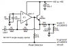
I am making a LM3915 VU meter but have one question about the peak detector.

I build this circuit: https://img.photobucket.com/albums/v222/ahhh/circuit_LM3915.png

This is working... not the way I want but is working....

I saw on the datasheet that is good to do a peak detector.

I have some TL071, TL081, TL082 and some LM358....

Can I use them to make the peak detector? May someone can help me with this circuit? Or maybe just do the peak detector with the PNP transitor?

Also another question, i saw on the datasheet that some circuits have a resistor typically 10k or 20K from +5V to the pin 1 or pin 9. Why? What is the function of them?

So, thanks.
 
Last edited:
The datasheet of the LM3915 shows a peak detector circuit using a single transistor. Its input signal must be about 10V peak because it does not work properly with lower levels.
A precision half-wave peak detector circuit and a precision full-wave peak detector circuits are shown but they need a dual-polarity supply to power their opamps.

An LM358 is poor for audio because it is noisy and has a poor frequency response. A TL071 and TL072 opamp are low noise, have a wide frequency response and are excellent for audio.

I used an MC33171 single-supply opamp in my Sound Level Indicator project because it has a frequency response much better than an LM358. An MC33172 is a dual and an MC33174 is a quad. Here is my peak detector circuit:
 

Attachments

  • peak detector.PNG
    peak detector.PNG
    16.2 KB · Views: 2,397
If I use the TL071, do I need to power it with +VCC and VCC/2?

Well, let's see if I can find the MC33172 here in my city.......

Can i change the 2N3904 for the BC546?

Now I going to shop this parts, later I will mount the, test, take some pics and post the result.

Thanks.
 
If I use the TL071, do I need to power it with +VCC and VCC/2?
No.
In a peak detector circuit it needs a positive supply and a negative supply because in a single polarity supply circuit its inputs do not work if they are a few volts from ground and the output does not go anywhere near ground.

Well, let's see if I can find the MC33172 here in my city.
The MC33171, MC33172 and MC33174 opamps work perfectly with a single polarity supply and the inputs work perfectly all the way down to ground. The outputs go down very close to ground.

Can i change the 2N3904 for the BC546?
Yes.
 
The simulation might be almost correct but is difficult to see on your simulation.
The output should drop to half level about 0.017 seconds after the sound beat has ended.
Your value for C3 is 1/3rd of mine so mine holds up the output peak 1.5 times longer.
 
Status
Not open for further replies.

New Articles From Microcontroller Tips

Back
Top