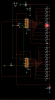
I have added pin numbers by hand and update the above schematic.
Thanks, but it is still a negative pic. It should have dark lines on a white background.
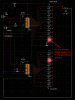
Do you mean the connections are not required between IC2 pins 9 and 11; IC2 pin 1 IC1 pin 9 ?
The datasheet shows how to do it. In the BAR mode, you are shorting pin11 to the positive supply so its LED will never light.
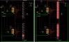
The second LM3914 has its pin9 connected to its pin11 (but not to the positive supply) only in the DOT mode. Then pin11 has a 20k resistor to the positive supply so that pin9 is high when the LED is turned off.