breakshift
Member
Hi all. A while ago I started looking into designing a heterodyne bat detector circuit. I posted a thread on here to ask for advice. So for reference you can find this thread here:
https://www.electro-tech-online.com...sducer-for-bat-detector-project.126293/page-2
Since then I've made some progress and I nearly have a working prototype ready, at least I think I do. It's all on a breadboard at the moment as I'm constantly fiddling with it. The main reason I'm starting a new thread is because I have an issue that I can't resolve. I'm not experienced with practical electronics, but I have fairly recently begun enjoying it as a hobby. So this may be a fairly common problem, I'm not sure.
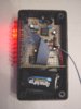
Basically the circuit I have at the moment is a MEMS microphone (with decent ultrasound performance), a voltage-controlled oscillator (square wave) set to 45kHz, a double balanced mixer IC, low pass filter and a LM386 audio amp feeding headphones. I've uploaded a simplified schematic of this; the microphone circuitry is replaced with a 40kHz sinusoidal signal, and I've not included the 10k linear pots to control the amplitude of the two inputs to the mixer IC, and the input to the LM386. I've also used a 40kHz piezo ultrasound emitter to create a simple transmitter circuit that I'm using to generate a nice clean sinusoid on the receiver circuit.
Before I get to my main issue, I have a question about the output of the mixer IC. With reference to the attached scope screenshot "3. Filter Output.bmp", channel 1 (yellow) is the receiver signal (attenuated to approx. 250mVpp), channel 2 (green) is the square wave oscillator (also attenuated to approx. 250mVpp), channel 3 (blue) is the direct output of the mixer IC, and channel 4 (pink) is that signal after filtering. I'm fairly concerned with how the signal on channel 3 looks. I'm expecting a signal of approx. 5kHz (difference between receiver 40kHz and oscillator 45kHz), which you can just about see in that waveform. Having measured the low freq component it is indeed 5kHz. But clearly something isn't right with that signal. The mixer claims to be double balanced, which means neither of the input signals should be present on the output, but clearly the square wave is dominating that signal! The filter clears it up nicely, but it could be better - surely the mixer output has gone wrong somewhere?
The filtered signal then goes to the LM386, and my main issue relates to this audio amplification stage. With the headphones disconnected, everything seems okay (to me at least). In reference to the scope screenshot "4a. Without Headphones.bmp", channels 1 and 2 are as before, channel 4 is the filter output signal, and channel 3 is that signal after LM386 amplification. There's a fair bit of noise there but the signal is more or less a 5kHz sine wave. Now when I connect up a pair of headphones, the LM386 output goes a bit wild. This can be seen from screenshot "4b. With Headphones.bmp" - I don't even know how to describe it, it looks like some kind of high frequency oscillation but of a periodic nature. You can see that the distortion is somehow feeding back right through the circuit, as you can see it's present on the mixer input pins. Perhaps it's something to do with the power supply (which is just a 9V battery, by the way, with 0.1uF decoupling cap). Don't know how to troubleshoot this really. Using the pot on the LM386 input, I've varied the input voltage and this behaviour is consistent right down to almost zero input voltage, although the periodic bursts become less frequent and the audible pitch from the headphones (horrible sound!) reduces significantly. I've also varied the square wave oscillator frequency from DC and up, and the distortion remains present throughout (varying in burst frequency and pitch etc.) except for above approx. 85kHz where it stops. I've also played with the transmitter frequency, and it remains more or less throughout, except for portions of spectrum where the signal amplitude drops to close to zero (frequency response of the transmitter and receiver are both fairly erratic so this happens at a number of points over the spectrum).
So, any ideas on this one? Any help or advice is appreciated")
https://www.electro-tech-online.com...sducer-for-bat-detector-project.126293/page-2
Since then I've made some progress and I nearly have a working prototype ready, at least I think I do. It's all on a breadboard at the moment as I'm constantly fiddling with it. The main reason I'm starting a new thread is because I have an issue that I can't resolve. I'm not experienced with practical electronics, but I have fairly recently begun enjoying it as a hobby. So this may be a fairly common problem, I'm not sure.
Basically the circuit I have at the moment is a MEMS microphone (with decent ultrasound performance), a voltage-controlled oscillator (square wave) set to 45kHz, a double balanced mixer IC, low pass filter and a LM386 audio amp feeding headphones. I've uploaded a simplified schematic of this; the microphone circuitry is replaced with a 40kHz sinusoidal signal, and I've not included the 10k linear pots to control the amplitude of the two inputs to the mixer IC, and the input to the LM386. I've also used a 40kHz piezo ultrasound emitter to create a simple transmitter circuit that I'm using to generate a nice clean sinusoid on the receiver circuit.
Before I get to my main issue, I have a question about the output of the mixer IC. With reference to the attached scope screenshot "3. Filter Output.bmp", channel 1 (yellow) is the receiver signal (attenuated to approx. 250mVpp), channel 2 (green) is the square wave oscillator (also attenuated to approx. 250mVpp), channel 3 (blue) is the direct output of the mixer IC, and channel 4 (pink) is that signal after filtering. I'm fairly concerned with how the signal on channel 3 looks. I'm expecting a signal of approx. 5kHz (difference between receiver 40kHz and oscillator 45kHz), which you can just about see in that waveform. Having measured the low freq component it is indeed 5kHz. But clearly something isn't right with that signal. The mixer claims to be double balanced, which means neither of the input signals should be present on the output, but clearly the square wave is dominating that signal! The filter clears it up nicely, but it could be better - surely the mixer output has gone wrong somewhere?
The filtered signal then goes to the LM386, and my main issue relates to this audio amplification stage. With the headphones disconnected, everything seems okay (to me at least). In reference to the scope screenshot "4a. Without Headphones.bmp", channels 1 and 2 are as before, channel 4 is the filter output signal, and channel 3 is that signal after LM386 amplification. There's a fair bit of noise there but the signal is more or less a 5kHz sine wave. Now when I connect up a pair of headphones, the LM386 output goes a bit wild. This can be seen from screenshot "4b. With Headphones.bmp" - I don't even know how to describe it, it looks like some kind of high frequency oscillation but of a periodic nature. You can see that the distortion is somehow feeding back right through the circuit, as you can see it's present on the mixer input pins. Perhaps it's something to do with the power supply (which is just a 9V battery, by the way, with 0.1uF decoupling cap). Don't know how to troubleshoot this really. Using the pot on the LM386 input, I've varied the input voltage and this behaviour is consistent right down to almost zero input voltage, although the periodic bursts become less frequent and the audible pitch from the headphones (horrible sound!) reduces significantly. I've also varied the square wave oscillator frequency from DC and up, and the distortion remains present throughout (varying in burst frequency and pitch etc.) except for above approx. 85kHz where it stops. I've also played with the transmitter frequency, and it remains more or less throughout, except for portions of spectrum where the signal amplitude drops to close to zero (frequency response of the transmitter and receiver are both fairly erratic so this happens at a number of points over the spectrum).
So, any ideas on this one? Any help or advice is appreciated