Continue to Site

Welcome to our site!

Electro Tech is an online community (with over 170,000 members) who enjoy talking about and building electronic circuits, projects and gadgets. To participate you need to register. Registration is free. Click here to register now.

  • Welcome to our site! Electro Tech is an online community (with over 170,000 members) who enjoy talking about and building electronic circuits, projects and gadgets. To participate you need to register. Registration is free. Click here to register now.

LM386 Amplifier Project

Status
Not open for further replies.

TheNewGuy

Member
Hello Everyone,
I had a few doubts on an mini amplifier project I have going.

I'm new to electronics, I've been practicing soldering and I've been reaserching and learning about electrical engineering on the internet.

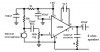
I came across a schematic (Click here) for a mini-amplifier project you could do.

I currently have most of my parts but right now, but I need the 100K Variable Resistor, the LM386 IC and the 0.1 uF capacitor. Where are these tipically found? I heard you can find the LM368 in answering machines and old modems. The only variable resistor I have right now isn't 100K, but 125K.

Also, what kinds of things ruin the sound quality on a project like this? I'm hoping to get good sound quality. What should I expect?

This is the first electrical project I've done, and I'm hoping to learn alot, so any advice would be apprciated.

Thanks Everyone,
-TheNewGuy
 
Last edited:
The circuits are missing one imporatnt resistor and two important capacitors that are shown on the datasheet of the LM386.

You do not want to have the electret mic anywhere near the speaker to avoid acoustical feedback howling.

A corrected circuit is here:
 

Attachments

  • LM386 with mic.PNG
    LM386 with mic.PNG
    13 KB · Views: 28,007
I forgot to mention, for both the imput and output I plan to put auxilary jacks. So you can connect your ipod to the imput, and your headphones to the output.

Would this work?
 
I forgot to mention, for both the imput and output I plan to put auxilary jacks. So you can connect your ipod to the imput, and your headphones to the output.

Would this work?
The OP of the 386 will certainly drive headphones but the volume might be too high. You may need to "divide down" the input signal some so your volume control is from no sound to loud sound, and not from no sound to blown eardrums. If the gain is set up for a microphone, the IPOD output is probably a little too high.
 
Last edited:
The circuits are missing one imporatnt resistor and two important capacitors that are shown on the datasheet of the LM386.

You do not want to have the electret mic anywhere near the speaker to avoid acoustical feedback howling.

A corrected circuit is here:

would it matter if I repaced the mic with an aux Jack like I said? (and the same with the speaker?)
 
If you replace the low level mic with a high level AUX input then the gain of the LM386 must be set to only 20 and a volume control must be used to reduce the input level. The resistor that powers the electret mic must be removed. a resistor attenuator must be used to feed headphones so that a loud signal does not deafen you.
 
audioguru said:
If you replace the low level mic with a high level AUX input then the gain of the LM386 must be set to only 20 and a volume control must be used to reduce the input level. The resistor that powers the electret mic must be removed. a resistor attenuator must be used to feed headphones so that a loud signal does not deafen you.

Ok, so the schematic you posted earlier should work right?

What is a resistor attenuator?
 
What is the part that says "220 nF film"? Is it a capacitor? I haven't seen anything measured in "nF" yet, just "uF". Is this component vital?

EDIT:
It is a type of capacitor, I think?

Also:
220 nF = 0.22 uF
 

Attachments

  • Part.PNG
    Part.PNG
    1.8 KB · Views: 2,202
Last edited:
What is the part that says "220 nF film"? Is it a capacitor? I haven't seen anything measured in "nF" yet, just "uF". Is this component vital?

EDIT:
It is a type of capacitor, I think?

Also:
220 nF = 0.22 uF

uF = F x 10 (EXP-6)

nF = F x 10 (EXP-9)

pF = F x 10 (EXP-12)


"FILM" is a type of capacitor. It is most commonly polyester film or polypropolene film. These type of caps have very low series resistance and inductance which makes them ideal for high frequency applications.

They are overkill for audio. Ceramics would work fine and are a lot cheaper and smaller.
 
Last edited:
Ceramic capacitors are terrible for coupling audio. they cause distortion and are microphonic. Film capacitors cost pennies and are perfect.
 
Ceramic capacitors are terrible for coupling audio. they cause distortion and are microphonic. Film capacitors cost pennies and are perfect.
If you say so.

For the record, I used them in a discrete headphone amplifier design and the measured THD was microscopic (measured on wave analyzer). I'm driving Sennheiser Studio reference phones, and I do believe I would hear distortion.

Any actual data showing measurable distortion in an amp with ceramic capacitors in place which is then "cured" (ie, distortion vanishes) by installing a film capacitor? Key word is "measurable" distortion, not "warmth", "presence", "natural timbre", "spaciousness", etc. but an actual distortion.

I knew ceramics might have a piezo effect if somebody stands on them, but I didn't know they spontaneously became microphones?


EDIT TO ADD:

OK, here's what I found:

Ceramic caps do induce distortion....


About 75dB down translates to something like 0.017% distortion. 70dB is about 0.03%. I think I can live with that.:p

Explains the reason I didn't find anything much in the headphone amp when I ran the distortion.
 

Attachments

  • THD.pdf
    12 KB · Views: 361
Last edited:
Ceramic capacitors are terrible for coupling audio. they cause distortion and are microphonic. Film capacitors cost pennies and are perfect.
Well, I don't think they cost pennies because we had to always use films for coupling caps in our power converters and they are quite expensive. The main problem being, the smalles V ratings for film types were like 50V which meant they were huge in size even to get small capacitance values.
 
At Newark today, a Vishay 220nF 10% 63V film capacitor costs only $0.45US for one. It is tiny. Other manufacturers might cost less.

A ceramic capacitor changes its value with voltage (signal) so at low frequencies makes even harmonics distortion. It picks up sounds because it is microphonic. Its value is not very accurate.

I just dug up the THD data I took off my discrete headphone amp which used some 4.7uF ceramic coupling caps at the front end. These are large discrete caps with leads, not SMD. I guess they didn't have a problem, because distortion is non existent.

I took some THD (total harmonic distortion) measurements using a Sound Technology 1701A distortion analyzer:

Test conditions: Rload = 47 Ohms (resistive).

VOUT = 100mV (rms) = 282mV (p-p)
20Hz: 0.056%
200Hz: 0.056%
2kHz: 0.056%
20kHz: 0.056%


VOUT = 500mV (rms) = 1.41V (p-p)

20Hz: 0.013%
200Hz: 0.012%
2kHz: 0.013%
20kHz: 0.015%


VOUT = 1.0V (rms) = 2.82V (p-p)

20Hz: 0.006%
200Hz: 0.006%
2kHz: 0.006%
20kHz: 0.017%
 
Last edited:
On his website, **broken link removed**
Rod Elliot measured 3% distortion across a ceramic capacitor that was attenuating its own distortion so its distortion was worse.
 
Last edited:
Hmm...when I go to the Shack for parts, I'm going to compare the two.

But I do need a resistor attenuator? How do I implement one into this amp?

Thanks for the advice guys, I really appreciate it. I'm a rookie at this, and I really want to learn.
 
On his website, **broken link removed**
Rod Elliot measured 3% distortion across a ceramic capacitor that was attenuating its own distortion so its distortion was worse.
What I said was, did they take THD data with ceramic caps and find it was high and then change and find it was low?

That's really the whole question. The data I put up is what I got off my discrete headphone amp, as far as I know the schematic is accurate. I have some large 4.7uF ceramics I used which have leads. If they were really bad, the measured distortion should have showed it.

No question ceramics might have more distortion than film caps. Question is: is it enough to measure or hear?
 
Hmm...when I go to the Shack for parts, I'm going to compare the two.
I'd be interested in finding out if you can hear any difference between a ceramic coupling cap and a film cap, with other things keep equal. Maybe to find out: build two and have an accomplice randomly switch the same music to one or the other and have you guess ceramic or film?

You should get at least 50% right by random chance.....:D

Since you are building two amps anyway (for stereo) you could put ceramic in one and film in the other then rig it to play a single channel through one or the other with a selector switch and see if you can hear the difference.

I'd be interested to know.
 
Last edited:
Status
Not open for further replies.

Latest threads

New Articles From Microcontroller Tips

Back
Top