TheNewGuy
Member
I'm trying to use Eagle Software to draw out the schematic, and I'm thinkin' of just using paint to draw it out. 
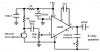
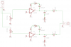
I'm just using this schematic as a basis so I have an idea where things should go. I'm going to add an attentuator at the output. Which would consist of a couple of resistors, as said before? (Correct me if I'm wrong). I looked at the box for my earbuds, and they are rated at 16 Ohm.
EDIT: I've changed my libraries from this link: here
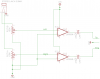
Much better!
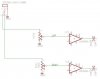
Of course all the grounds are connected together and the +9V points are connected together.
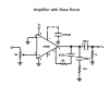
This circuit does not have a resistor attenuator at its outputs so it might deafen you. Read the text of its article to see the impedance of their headphones or how they prevent the sound to be too loud.
I'm just using this schematic as a basis so I have an idea where things should go. I'm going to add an attentuator at the output. Which would consist of a couple of resistors, as said before? (Correct me if I'm wrong). I looked at the box for my earbuds, and they are rated at 16 Ohm.
EDIT: I've changed my libraries from this link: here
Much better!
Last edited: