MrDEB
Well-Known Member
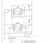
assembled the pocket theremin that shows 2 - 555's
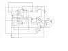
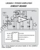
I redid using a 556 and added a LM386 amp.
Not realizing the speaker is connected directly to power (orginal design using 2-555's) so the 555 is sinking not sourcing.
Well I put an LM386 into the mix and realize my error when I have virtually no sound.
Looking at both schematics, how can I insert an LM386 into the circuit??
Thinking about the pot being connected between power and pin 9 then the wiper connected to pin 3 of the LM386??