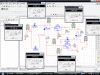
There's still trouble.
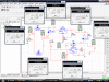
How are the gates being switched?
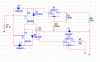
unless the solar panel is in the dark, it's output will always have some voltage to it as a solar panel is a constant voltage source.
the input to the second lm317 with the negative side to the battery is not going to fly either. the adjust line is at ground.
Grab a hunk of perf-board and build just the battery and u2 connected to each other, then apply voltage with your power supply to the + side of the battery. see what happens in the real world.
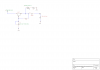
if you are only after a charge controller, use one lm317 set up for a constant voltage source. set the output of the lm317 to whatever the full charge voltage of the battery back is. Let's say your charging a small lead-acid battery. A 12 volt pack is fully charged at 14.3 volts (depends on the company) so set the output of the regulator to 14.7 volts and then insert a diode between the output and the battery to prevent discharge at night.
when the battery voltage reaches the voltage set by the lm317, charging current stops or drop to a very small amount to keep the battery fully charged.