Continue to Site

Welcome to our site!

Electro Tech is an online community (with over 170,000 members) who enjoy talking about and building electronic circuits, projects and gadgets. To participate you need to register. Registration is free. Click here to register now.

  • Welcome to our site! Electro Tech is an online community (with over 170,000 members) who enjoy talking about and building electronic circuits, projects and gadgets. To participate you need to register. Registration is free. Click here to register now.

LM317 CIRCUIT IADJ CAPACITOR FAILURE

Status
Not open for further replies.

DND

New Member
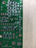
Hi, We have a voltage regulator circuit having 24 volts DC input and 5 volts ,0.5 Amperes output and facing failure of the 10mfd/16 volts chip capacitor attached to the adjustment pin of the LM317. Can anybody explain the root cause of this failure please. The circuit is attached.
 

Attachments

  • lm317 power supply.jpg
    lm317 power supply.jpg
    45.3 KB · Views: 233
I have looked at this already, but did not answer as I cannot see any practical reason for such a failure.
It has to be a guess, that either the cap was faulty or fitted backwards.

Please do not post in multiple categories as it just confuses things - and keep normal questions to the public forum, so other people can benefit from any solutions..
 
There's no polarity shown on the capacitor, and there should be, unless it's not an electrolytic.
 
  • Like
Reactions: DND
10uf/16v is usually an electrolytic. polarity? or are the chip caps tantalums, in which case OP should go with a voltage rating of 30 or 50V.
 
  • Like
Reactions: DND
BTW) You can get chip capacitors that cover that voltage and capacitance rating that are non polar.

EDIT:
There must be something else ... as mentioned perhaps it IS a capacitor with polarity and it is the wrong way.... That circuit should regulate to about 5.11 Volts with a slow rise when power is applied due to the cap in question. If you remove the cap all together the voltage will be at 5.11 Volts as soon as the input supply is provided. Otherwise there is only about 6mA of current the capacitor would ever see. Hardly enough to cause it to fail. Even if it were reversed. I think there may be something wrong with the PCB layout, because the schematic looks to be correct. I would also check the pinout of the regulator itself .... I have been burned in the past assuming it was always one way. Some manufacturers and package styles like to swap the pins around.
 
Last edited:
  • Like
Reactions: DND
10uf/16v is usually an electrolytic. polarity? or are the chip caps tantalums,
This is a nit, but tantalums are electrolytic, along with niobium and the more common aluminum variety.
 
  • Like
Reactions: DND
Thank you all for your replies. The capacitor used is automotive chip multi layer ceramic capacitor part number GCM31CR71C106KA49 of Murata make. We have produced around 450 numbers of the same circuit and out of that 14 numbers failed during internal testing and now 1 number failure reported from customer end. I have to do a defect investigation and was seeking your help. Any suggestions on this regard is welcome.
 
Can you provide a picture of the PCB with and/or without components populated? There could be a spot where a potential solder bridge could occur during manufacturing. i.e. if a via is too close to a solder pad ... I have seen this sort of thing before where the "same" board works without a problem, and then you have a batch that have all the same issue. Another question, have you changed board houses where you are having the PCB's made... even the same board house for that matter. If there is a potential for a "close" tolerance, then any kind of misalignment could cause some boards to fail while others are fine.
 
  • Like
Reactions: DND
Thank you for the reply. The bare PCB and populated PCB photos are attached. The capacitance reference is C9. We are getting the PCBs done from the same source in batches of 100 numbers. Soldering of components are done inhouse. The failure is not from the same batches of manufacturing.
 

Attachments

  • BARE PCB.jpg
    BARE PCB.jpg
    102.7 KB · Views: 204
  • POPULATED PCB.jpg
    POPULATED PCB.jpg
    91.8 KB · Views: 203
Could it be mechanical stress, if they are being hand soldered to a cold PCB?

The cap will be expanding from soldering heat but without the PCB also being at a similar temperature, there would be more differential expansion and contraction. As it cools it will shrink slightly and try to pull itself apart.

Just a theory...
 
  • Like
Reactions: DND
I do this sort of thing all the time and thermal effects from hand soldering shouldn't be a problem unless you are just spending a ridiculously long time soldering the components and I don't see any evidence of scorching on the populated board. Not that it is a problem, but things I would look out for are the vias near R15/D6 and R19 for possible unwanted solder bridging. I'm concerned about the screw terminal near R2 I assume this is your 5V output? Is there a possibility that screw could be over tightened and crush the PCB? That screw looks like it has a beveled head (great for crushing under tension), a better option might be one with a flat head. In the images below the screw head to watch out for is the beveled one on the bottom. The other image just shows them in my application.
 

Attachments

  • 20200124_005050.jpg
    20200124_005050.jpg
    826.6 KB · Views: 182
  • Capture.PNG
    Capture.PNG
    524.7 KB · Views: 190
  • Like
Reactions: DND
Thank you for the reply .We are going to have a discussion regarding this today in our office including the above points and come back soon. I have also contacted the LM317 Manufacturer and he is suggesting this as a random failure and asking me to contact the capacitor manufacturer Murata, and I have sent a mail to them and waiting for the reply.
 
Very interesting discussion to me and I am curious as to whether you can get to the bottom of the problem.

The attribution of "random failure", is, in my view, weasel words. 14/450= a failure rate of .031. For the heck of it, I looked around to see some listed failure rates of capacitors e.g., https://www.holystonecaps.com/failure-rates/ and, if I am reading correctly, the rates are well below that at 'normal' temps - I welcome corrections as I am not an EE and believe that I could solder my fingers together, with enough flux.

I wish you had more data on the 14 failures uncovered in testing. Thermal image, test point voltage and current - that kind of thing.
 
High value non-polarized chip caps are made of of many layers and are subject to stress failures. Were the boards hand-soldered with an iron? If so, I'd suggest focusing on thermal stress caused by uneven heating.

Using hot air and solder paste might be more reliable with reflow soldering being best.
 
"I have also contacted the LM317 Manufacturer " ... Not sure that it would be their fault... to isolate the capacitor as being the culprit beyond a doubt, what happens on a "failed" board if you remove C9 entirely? You regulator will still function, it just wont have a slow voltage rise as I mentioned in post #5
 
  • Like
Reactions: DND
LM 317T user here. For a long time. Never had a chip fail. Never seen your particular problem. I'm talking years and years of running them just within max dissipation and thermal specs.

Maybe your LM317T's are a bad batch causing that cap to fail. I'm scratching my head. No. That doesn't make sense.

There is something about the board layout or cap quality that makes more sense. It's a small thing causing the crap. I dunno what else to say.
 
High value non-polarized chip caps are made of of many layers and are subject to stress failures. Were the boards hand-soldered with an iron? If so, I'd suggest focusing on thermal stress caused by uneven heating.

Using hot air and solder paste might be more reliable with reflow soldering being best.

Big Clive recently posted a video with a failed LED light where a high value SMT cap failed. Starting st around 9:00 in the video he shows how these multilayer caps are made and why thermal stress can kill them. This failure mode would be greatly exacerbated by hand soldering with an iron.
 
  • Like
Reactions: DND
It could be mechanical stress on the capacitor. Any bending of the board will cause the capacitor to be stressed, and the ceramic can crack. The crack can provide a path for electromigration between the +ve and -ve layers, resulting in a short.
 
  • Like
Reactions: DND
Just curious, what does the power supply to the regulator look like? Is it noisy I wonder? What does the load look like? Might be a source of mechanical stress (piezo effect) on the capacitor.
I'm just throwing an idea out there, I'm not even sure what that capacitor node would look like if the power supply did happen to be dirty.


Reference:
**broken link removed**
 
  • Like
Reactions: DND
Good day to all from India!!!!! The power supply to the regulator is from 24 volts battery of the earth moving vehicle. This unit has undergone and passed all input voltage variation and spikes tests upto 1000 volts DC for 2 secs. :D
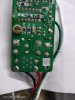
. This 5 volts is used to drive a micro controller and relays. We have replied to the customer stating that this failure may be due to mechanical stress on the capacitor while soldering.
 
Status
Not open for further replies.

New Articles From Microcontroller Tips

Back
Top