upand_at_them
Active Member
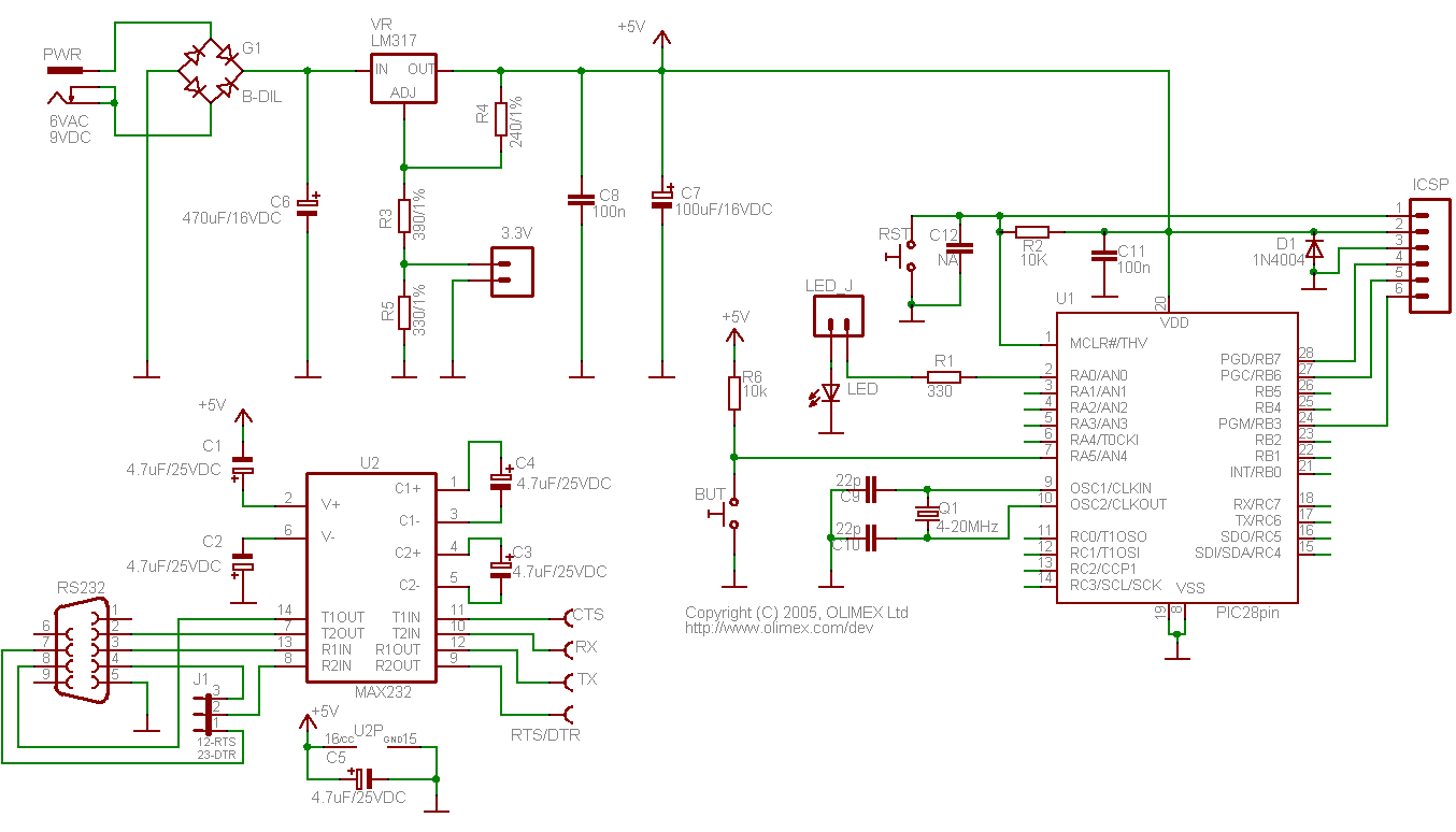
I saw this PIC development board, which has the feature of getting two outputs from the LM317. Interesting, I though. But in the LM317 datasheet the adjustment pin current is a maximum of 100uA, which wouldn't be enough to power anything. So is this design legitimate? I suppose the 3.3V output could be taking current from the actual 5V output? But wouldn't any change in current draw from the 3.3V output change the voltage drop across R4? Also, unless my math is wrong, the voltage at the adjustment pin has to be 7.2V in order for the R5/(R3+R5) voltage divider to output 3.3V.


