Continue to Site

Welcome to our site!

Electro Tech is an online community (with over 170,000 members) who enjoy talking about and building electronic circuits, projects and gadgets. To participate you need to register. Registration is free. Click here to register now.

  • Welcome to our site! Electro Tech is an online community (with over 170,000 members) who enjoy talking about and building electronic circuits, projects and gadgets. To participate you need to register. Registration is free. Click here to register now.

LM317 protection

Status
Not open for further replies.

ataul

Member
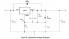
I faced some problem with my LM317 power supply, when i need to check 48 volt circuit, i do connect two power supply in series to get 48volt or so. but if suddenly two terminals (48V) are short circuited the LM317 power supply is blow up and 120Ohm resistor (hooked output to Adj pin) also blow. I insert all protection diode as recommended but i don't able to protect LM317. My other PSU was fixed 30V 2.5A SMPS.
please suggest me what can i try to do others way to protect LM317.
 
What is output load impedance and voltage at time of input short to ground.


edit...

Show block diagram of two input series supplies , your design , load capacitance , current and voltage and where is 30V SMPS?

Is there large series input inductance (uH) between source and where short to ground was applied?
If so, then inductive kickback (+) V=L*di/dt when short is removed and if pot is set to 0,
Absolute MAX input output differential is 37Vmax.

Otherwise consider increasing both Pot and Fixed R 240 values so you never exceed power dissipation with >>> 1.25V across resistor from a shorted input.

Just guessing since you did not provide details on design.
 

Attachments

  • upload_2015-11-7_6-33-21.png
    upload_2015-11-7_6-33-21.png
    18.3 KB · Views: 212
Last edited:
When you are stacking the regulators and connect a load, each regulator is seeing a voltage between the output pin and the common pin that is higher than the regulator will accept, when a short-circuit occurs. It is the high voltage that blows one up then the other.
 
Its not clear to me how these are stacked, Colin. I can think of many problems and solutions, however without more info, the problem is unclear.

Perhaps a series diode to input to LM317 and reverse diodes across both stacked input regulator outputs to prevent reversal surges on a shorted output... to the input of the LM317.

Exactly how it is wired is still a mystery.
 
What is output load impedance and voltage at time of input short to ground.


edit...

Show block diagram of two input series supplies , your design , load capacitance , current and voltage and where is 30V SMPS?

Is there large series input inductance (uH) between source and where short to ground was applied?
If so, then inductive kickback (+) V=L*di/dt when short is removed and if pot is set to 0,
Absolute MAX input output differential is 37Vmax.

Otherwise consider increasing both Pot and Fixed R 240 values so you never exceed power dissipation with >>> 1.25V across resistor from a shorted input.

Just guessing since you did not provide details on design.[
Hea
What is output load impedance and voltage at time of input short to ground.


edit...

Show block diagram of two input series supplies , your design , load capacitance , current and voltage and where is 30V SMPS?

Is there large series input inductance (uH) between source and where short to ground was applied?
If so, then inductive kickback (+) V=L*di/dt when short is removed and if pot is set to 0,
Absolute MAX input output differential is 37Vmax.

Otherwise consider increasing both Pot and Fixed R 240 values so you never exceed power dissipation with >>> 1.25V across resistor from a shorted input.

Just guessing since you did not provide details on design.

Here is the circuit
 

Attachments

  • 317.bmp
    385.1 KB · Views: 209
within a micro second LM317 Malfunctioning then when i rotate pot to zero full current flow throw 220 Ohm resistor via pot wiper to LM317 ground and 220 Ohm resistor burnt out.
 
what is the stackup? that causes microsecond malfunction? Sketch a a diagram of all connections.

You cannot simply put a pot on a 48V regulated output to ADJ. THe max differential Voltage is 37V and 220V 1/4W can only handle a the 1.25V drop across it.

Add a series fixed R to the pot to limit minimum range. Consider input forward diode to prevent input shorting to gnd so it floats if input before diode is shorted.

Show complete schematic Like I did except show all inputs and outputs and where short occurs.

correct any assumptions I made below

https://www.electro-tech-online.com/attachments/upload_2015-11-7_6-33-21-png.95162/
 
When the combined output is short circuited there will be over 60 volts between the input and output orf the LM317 (The unregulated input to the LM317 plus the 30 volts from the switch mode PSU.) I suggest putting a large diode (10 amp or larger) across the output of the LM317 regulator and adding a 1 amp fuse to the output og the LM317 regulator. (The diode should be on the LM317 side of the fuse.) This way the output of the LM317 will not be forced more negative than about 0.7 volts when there is a short.

Les.
 
upload_2015-11-7_15-53-31.png

upload_2015-11-7_15-54-26.png


For next time.......

upload_2015-11-7_16-0-8.png
 

Attachments

  • upload_2015-11-7_15-49-53.png
    upload_2015-11-7_15-49-53.png
    39.5 KB · Views: 167
Last edited:
Fantastic Idea Tony !!! it could be a good idea for over 36 volts variable single source power supply when i have not any source of over 30Volts I will implementing this farther next project.
In study of popular 317 protection issue Les jones here elaborate here why LM317 fails in sort circuit condition.may be he is in correct way i will testing this now.thanks to Les jones.
 
When the combined output is short circuited there will be over 60 volts between the input and output orf the LM317 (The unregulated input to the LM317 plus the 30 volts from the switch mode PSU.) I suggest putting a large diode (10 amp or larger) across the output of the LM317 regulator and adding a 1 amp fuse to the output og the LM317 regulator. (The diode should be on the LM317 side of the fuse.) This way the output of the LM317 will not be forced more negative than about 0.7 volts when there is a short.

Les.
Hi les Jones is this way?
 

Attachments

  • PSU.bmp
    385.1 KB · Views: 166
Hi ataul,
Yes, that is what I meant. I have also just noticed that you do not have a capacitor from the output of the LM317 to ground as shown in the data sheet. I think building a supply designed for the voltage you require as suggested by Tony would be a better solution than connecting supplies in series.

Les.
 
Status
Not open for further replies.

Latest threads

Back
Top