Continue to Site

Welcome to our site!

Electro Tech is an online community (with over 170,000 members) who enjoy talking about and building electronic circuits, projects and gadgets. To participate you need to register. Registration is free. Click here to register now.

  • Welcome to our site! Electro Tech is an online community (with over 170,000 members) who enjoy talking about and building electronic circuits, projects and gadgets. To participate you need to register. Registration is free. Click here to register now.

mosfet reverse battery protection

Status
Not open for further replies.

MrDEB

Well-Known Member
Presently using a diode for reverse battery protection on two different projects but want to improve my circuit design by using a P mosfet instead of the diode.
input is 4 AA batteries so 6v max
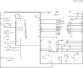
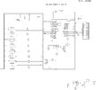
circuits have a pic mictocontroller that drive an 8 segment led matrix (have two circuits, the second drives an LCD display)
Have noticed that the LCD starts displaying little squares when battery voltage drops so adjusting the 10K pot gets to be an issue.
Selecting the right SMT P_mosfet is my challenge but am sure members have a favorite P-mos they use.
any suggestions?
 
What is the max current that your circuit draws from the battery? Need to know that to choose the mosfet.

Yes, a P mosfet is a better way of doing reverse polarity protection. The diode will always have 0.3V to 0.7V (depending of type) of loss, but the voltage loss of a properly sized mosfet can be near zero.
 
I recall measuring the current draw last year. Less than 2amps.
will remeasure again after I redraw my schematic
 
I finally got back to this project and using a digital multi meter set on MA it says .06
so 60ma is with some flashing leds.
 
I need to add the mosfet etc to my schematic. I have it included on another project but havn't measured the current as it has an LED matrix instead of an LCD.
 
here are both schematics
 

Attachments

  • mex trn 12-20-21.jpg
    mex trn 12-20-21.jpg
    564.4 KB · Views: 227
  • wicked 8.jpg
    wicked 8.jpg
    537 KB · Views: 234
P-channel MOSFET in series between the battery anode and the circuit power input. Source to the battery, Drain to the circuit, Gate to GND. Add a resistor from the Gate to the Source to guarantee rapid turn-off when the battery is disconnected. 10 K - ish.

ak
 
not sure about adding the 10k+ resistor. All the circuits I found use on resistor from Gate to Source
Pictured circuits are using an N channel mosfet
 
not sure about adding the 10k+ resistor. All the circuits I found use on resistor from Gate to Source
Not sure what "on resistor" means. It looks to me like there is a condition when the gate might be floating, not a good thing. Also, those look like p-channel devices.

With a max battery voltage of 6 V, what is the purpose of the 100 ohm gate resistor?

ak
 
Add a resistor from the Gate to the Source to guarantee rapid turn-off when the battery is disconnected. 10 K - ish.
Why do you need rapid turn-off at the input (source)?
 
Here's a good explanation of how this is supposed to work and the purpose of various components.


If you're impatient then around 1:50 into the video.

If you're working with a max of 6VIN you probably don't need the zener or gate resistor, but check the P-chan FET datasheet for max VGS.
 
Status
Not open for further replies.

Latest threads

New Articles From Microcontroller Tips

Back
Top