Continue to Site

Welcome to our site!

Electro Tech is an online community (with over 170,000 members) who enjoy talking about and building electronic circuits, projects and gadgets. To participate you need to register. Registration is free. Click here to register now.

  • Welcome to our site! Electro Tech is an online community (with over 170,000 members) who enjoy talking about and building electronic circuits, projects and gadgets. To participate you need to register. Registration is free. Click here to register now.

Nicad Battery Charging Protection

Status
Not open for further replies.
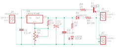
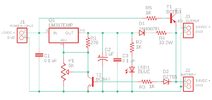
Hello. I'm trying to design this circuit to turn on an LED light when the power is out, I'll be using a 3.6VDC battery 1000mah. I'm getting lost with the charging protection (using zener diode) to limit current, but is not limiting voltage as I understood. Can someone take a look at the schematic and see what needs to be fixed? Many thanks.
(and I'm sorry if this solution has been posted prior, there are thousands of solutions on the site and was hard to filter, a reply here is appreciated).
 

Attachments

  • schematic.png
    schematic.png
    17.7 KB · Views: 228
Are you sure the batteries are nicads? Three nicads would give 3.6v but so will one lithium battery.

Mike.
 
You don't need anything fancy like that for NiCD cells.
They can stand a trickle charge at C/20 or less indefinitely - it actually keeps them in good condition.

Just use the series diode and resistor (D1 & R4) with a fixed voltage from the regulator; remove D2, T2 & R3.
The current should be down to C/20 or a bit less once the cells reach full charge voltage, which is near enough 4.5V for three cells.

With 1AH cells, C/20 is 50mA; as a convenient value, the 33R resistor with 1V across it would give ~30mA so set the reg output at about 6.1V; 4.5 + 1 + 0.6V
That would give an charge current with dead cells (1V per cell) of (5.5 - 3.0) / 33 = which is still only 75mA, so a very long charge time, roughly 24 hours or so.

You could reduce the resistor value quite a lot (and the voltage in proportion) to get a faster initial charge; eg. 10 Ohms and the reg set at around 5.5V, giving around 40mA trickle and 190mA initial peak charge.
 
awesome. I will remove D2, R3 and T2 all together, so it won't cutoff the battery when it reaches full charge. I understand this is to keep a trickle charge current on the battery to maintain it, correct? I will replace R4 with a 10ohm resistor per your suggestion! That will do for this circuit right?! Many thanks again for your help and quick replies!! :)
 
That looks fine.
Just set the regulator initially to about 5.5V, then as you first fully charge the cells check after a day on charge and adjust so there is near 0.4V across the ten ohm resistor; it's not critical, but ideally still around 0.3 - 0.4V once the cells have been on charge for several days.
 
A quick update!

Circuit works and charges the battery as expected. Thanks for all the help!

(I had previously posted a message talking about the voltages of the LED board and battery, disregard if you read that message, I had a wrong resistor in place, I'm using 0805 smd and one got mixed up, after replacing that resistor all is working well :)

Thanks again.
 
Last edited:
Status
Not open for further replies.

Latest threads

Back
Top