Continue to Site

Welcome to our site!

Electro Tech is an online community (with over 170,000 members) who enjoy talking about and building electronic circuits, projects and gadgets. To participate you need to register. Registration is free. Click here to register now.

  • Welcome to our site! Electro Tech is an online community (with over 170,000 members) who enjoy talking about and building electronic circuits, projects and gadgets. To participate you need to register. Registration is free. Click here to register now.

lm2917 frequency voltage converter, non linear output?

Status
Not open for further replies.
Lets do this design... for your case.... lets assume Fmax = 300Hz based on (4000 RPM * 4 (four cut flywheel?))/60sec = 264 Rounded up to 300.

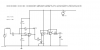
Your Vcc is your supply! Not the internal zener regulated voltage. Remember the collector emitter of your output transistor is driven by the supply.

Now...
Fmax = I2/(C1*Vcc)
Thus C1 < 50nF

Now... R1 >= V3Max /I3min (from datasheet)

You want 0 -5 V?

So R1 >= 5/140uA >= 35714

Thus R1 >35714

Now we solve

Vout = Vcc x Fin x C1 x R1

5 = 12 x 265 x C1 x R1

5/(12*265) = R1 x C1

R1 = 5/(12*265*c1)

If we assume standard cap values below 50nf ... 47nF, 33nF, 22nF and 10nf

If C1 = 47nF .... R1 = 33453 Not Applicable as R1 is too small
If C1 = 33nF .... R1 = 47646 Great using a 47k resistor should be good enough
if C1 = 22nF .... R1 = 71469 Good 68k resistor plus 10k trim pot allow good accuracy
if C1 = 10nF .... R1 = 157232 maybe bit too high

So I advise trying C1 = 33nF or 22nF and the appropriate resistor

Best of luck mate
 
Last suggestion...

10585-adcg.jpg
 
Last edited:
Thankjs bud your help is appreciated.

Can't do much today as I'm running low on components, but i'l try the values you suggested, and i've also placed an order for tonnes of shielding so i'l go over everything again with that.

Also trying to get hold of a scope so we can rule out noise.

Finally - i know we don't know much about the specific sensor, but is it possible to detect the ac directly with an analogue pin (perhaps through a diode)?

Just wondering if nothing seems to work, if that'd be a 'worst case scenario' solution - but i expect the ac voltage would be too low at low frequencies to be able to be picked up...
 
Dont stress too much about sheilding... :D

Highly possible... using a diode and some filtering and protection straight to an analog pin...
OR... I would feed the signal through a diode into a monostable 555 timer design. Take the timer output to a digital pin.

But stick with the 2917 its actually quite a good IC.

Cheers
 
Last edited:
But stick with the 2917 its actually quite a good IC.

Yes - rumour has it that it can save a lot of hassle! :p


...and I beleive it will. When I get it working :)


I can't do much more until my ordered gear comes, but I have been out with a multimeter and measured the ac signal, which seems to be about 1v at idle and once again rises.

Since I only need to count peaks, it shouldn't actually be too much of an issue either way, though I would rather use the lm2917 as taking an adc reading is much easier on the processor than having to pause my program at regular intervals to sample a delay...

I don't think that will matter the processing is fast but it's just how I preferred to roll on this one :)
 
What's the zener for?

Dakta, you may be picking up noise from your transducer due to flywheel surface irregularities, the radiator fan (it probably isn't running when you start the engine, though), or some other source. I would try a lowpass filter at the input to the LM2917. I was going to say that you could use a cutoff frequency of 500 Hz, but that assumes a 50% duty cycle signal. With pulse outputs from the sensor, a higher cutoff frequency is probably in order, like 10kHz, or possibly even higher. You could try a 10k resistor in series with the input pin, and a 1nF cap from the input pin to ground. This would give you a 16 kHz cutoff frequency, which would attenuate short pulses. I don't know how wide your legitimate pulses are, though, and they will get shorter as the RPMs increase, so 16kHz might also attenuate them too much. You could experiment with the values.
 
A scope really would help wouldn't it!

Right, i'l go buy some random bags of small capacitors and resistors and we'l have a mix match and solder session :D

Thanks you two :)

ps: I do beleive you may be onto something with the noise, I knocked the cable against the engine earlier and it stuttered, so I'l start with yet more shielding (and more earthing of it).
 
Last edited:
The cable shield should be grounded only on the circuit board, and not on the sensor end.
 
yeah thats how it is when its hooked up solely to the management system (but it raises a question when hooked up to my pcb - as in Y cable with sensor at the single end) - would that cause an issue?
 
Last edited:
yeah thats how it is when its hooked up solely to the management system (but it raises a question when hooked up to my pcb - as in Y cable with sensor at the single end) - would that cause an issue?
I don't think so, but it brings up another question - doesn't the engine computer have a tach output?
 
the lm2917 is unnecessary, look at this .asc. At 50 hz the out is 7.66 v, at 300 hz the out is 9.78. Use a voltage adder and add a -7 to it and multiply by 5 and you end up with an output of about 3 to 13 and that can be adjusted with the selection of the correct resistors.
Kinarfi
Ran the numbers, still not linear though, started with 300 hz and dropped by 50 hz steps
Hz-----V-----Diff
300 7.66
250 7.75 -0.09
200 7.89 -0.14
150 8.12 -0.23
100 8.56 -0.44
50 9.78 -1.22

Maybe some one else knows how to make it linear.
 

Attachments

  • lm2717.asc
    3.3 KB · Views: 185
  • LM2917.PNG
    LM2917.PNG
    11.3 KB · Views: 310
Last edited:
I don't think so, but it brings up another question - doesn't the engine computer have a tach output?

yes, well, sort of.

The engine computer does the calibration into revs then sends another signal to the dash unit (pulsed DC)...... - I think.

Whilst this may sound like a god send, I ruled it out as I want as small a install footprint as possible, for example I don't mind modifying sensors and such, but I don't want it to be hardwired into the car if you know what I mean, as it'l be swapped in and out of multiple cars (of the same make and engine), my t'eed crank sensor with it. It's a bit of a test unit I'm trying to build as my car doesn't conform to any diagnostic port standards.
 
Last edited:
Right guys, you deserve a bit of an update on this.

I ordered the components as mentioned the other day - I am still waiting for them to drop through the door.

I do believe progress has been made however, as a friend from another forum suggested using a tone generator app using my pc's soundcard to drive 'through the rev range' and test the signal.

With this set up, the signal was as dirty as ever, and as i removed the signal source from my pcb, i noticed it was still seeing a voltage from the IC.

So wondering if it could be the cable to the pcb, i lopped it off a centimeter from the board and watched as the adc input dropped by half.

So having a peice of wire connected to the pcb can disturb my readings, even if the other end isn't connected to anything, and it only takes a short length to have a big impact.

So i think i'm almost definitely dealing with interference/noise - by putting all cables away from the pcb and hiding it in a drawer I was able to go from (8 bit reading) 50 (out of 255) which was jumping beteeen about 40 and 60 right down to 17 in the drawer which would on;y jump between 15 and 19.

That 17 then, kept as far from interference sources as possible, must be the noise footprint of my circuit.

So seems I need to look into working with noise.
 
What voltage range of out put are you looking for to feed to your tach?
Kinarfi
 
Hopefully 0-5v for a range of up to 4000rpm (though 5000 would be nice but would be an extreme value).

4 pulses per revolution, so the stock circuit that's been thrown about here should be quite close one would think!
 
Can you post a picture of your PCB?
How about a picture of your entire physical setup?
 
I think it is breadboard interference pickup by the many long wires acting like antennas for mains hum and other interference.
 
I think it is breadboard interference pickup by the many long wires acting like antennas for mains hum and other interference.

I think you're right.

I've not tested it yet, but i've spent the evening with some conductive shielding tape, going over the full lengths of wires and earthing them at the breadboard end. I hope this helps.

If the circuit I made itself forms a significant part of the interference source, what is the best way of dealing with this? can I make some sort of enclosure with a bodged up faraday cage or something inside? - that might sound daft but I know little when it comes to shielding.

:p

Roff, I can post up a schematic if you'd like, though im fairly confident this is a noise issue. Not dead certain about the source, but sure there is noise.
 
Last edited:
I make all my prototypes on stripboard (Veroboard) so that the copper strips form half of a pcb and the parts and a few jumper wires form the other half of the pcb. It is compact and works very well at any frequency when its layout is planned properly. Almost every stripboard circuit I have made was sold including the very big and complicated ones.

I made one stripboard circuit for the head office of a new bank. They asked for a voice scrambler for their new wireless teleconferencing system. I designed it, built it, demo'd it and it worked perfectly. Then they soon went bankrupt for cheating. That is why they wanted voice scrambling.
 
Roff, I can post up a schematic if you'd like, though im fairly confident this is a noise issue. Not dead certain about the source, but sure there is noise.
We've seen a schematic. I would like to see a photo of your circuit - breadboard, PC board, or whatever you have - and also a photo of the entire setup, including the transducer, the circuit board, and the ADC. Maybe we can help locate the source of the noise (or oscillation) if we can see what you have.
 
Status
Not open for further replies.

Latest threads

New Articles From Microcontroller Tips

Back
Top