Continue to Site

Welcome to our site!

Electro Tech is an online community (with over 170,000 members) who enjoy talking about and building electronic circuits, projects and gadgets. To participate you need to register. Registration is free. Click here to register now.

  • Welcome to our site! Electro Tech is an online community (with over 170,000 members) who enjoy talking about and building electronic circuits, projects and gadgets. To participate you need to register. Registration is free. Click here to register now.

Lithium battery for a PHEV?

Status
Not open for further replies.

mading2018

Member
Hello,

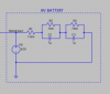
I trying to find a equivalent battery model for a PHEV (plug-in-electric vehicle)
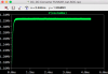
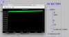
and simulate the charing process in LTspice.

I want the battery to have SOC=0, an empty battery from the begining, and starts to charge between the charging range of 320-380 V. I know the battery should have also an internal resistance, based on how many cells are connected in series.

Do you know how to design it or where I can found it?

I really appreciate all help I can get,

Thank you
 

Attachments

  • Lithium Battery - PHEV.asc
    472 bytes · Views: 198
The diode should have a high current rating. What is your charging current? I think you can have the voltage source step from 320V to 380V in time. (in seconds not hours)
Do you have a data sheet on the battery?
 
My charging current is relative high I would say, it says 265 A (max current).
Aha right, I need to change the axis to hours, I will check that.
I will come back to you regarding the data sheet. I will most probably have that next week.
 
I learned that the internal resistance could be approximately be 1-2 mohm per cell in series,
and 80-100 cells are usually implemented in PHEV battery, so I guess it should me around 160-200 mohm.

I can attach the file here with the battery including the DC/DC converter, so you can analyze the battery.

Have a nice weekend,

Thank you.
 

Attachments

  • DC_DC Converter FUNKAR 320V+Battery.asc
    5.3 KB · Views: 195
I think the battery should be more accurate. Even know, I do not know what I should set the values for the voltage source? Should it be zero? Cause i want the battery to empty from at initial Do you know a good way to get the SOC-value from the battery? I guess I need to implement some equation in the LTspice somehow.
 

Attachments

  • forum13.png
    forum13.png
    16 KB · Views: 230
  • DC_DC Converter FUNKAR 320V+Battery.asc
    5.4 KB · Views: 199
Have you tried to make a battery model using this approach?
 
I don't have such a file.
 
Okay. I know that my battery is having a charging range of 320-380 V and maximum current rate of 265 A. I believe that the nominal voltage is around 324 V where the battery capacity is 7.5 kW, which would give 23 Ah I think.

Do you know how I can get the SOC easily from my model in LTspice?
 
Your battery model doesn't have a SOC other than 'fully charged', because V6 is a perfect voltage source and so has infinite charge capacity.
I usually model a battery being charged as simply a high value capacitor, e.g. 1 Farad or so. An initial voltage on the cap can be set using the .ic directive, so that the sim runs in a manageable time.
 
I've just played with the post #6 approach. Here's the basis for a model of a single lithium cell :
CellModel.PNG

R1 represents the cell's ESR. The 2.9 figure represents the (unrealistic) cell voltage when charged. 100 is a convenient value, but the higher it is the greater is the cell's Ah capacity.

Edit: For your battery charging sim, try the model shown, but with R1 = 200m, the 100 value replaced by a number 25 times the battery's Ampere-hour capacity and the 2.9 value replaced by 380. Use the directive .ic V(battery)=320 to initialise the battery voltage at 320V, if that is where you want the charging to start.
 
Last edited:
Thank you very much alec_t. It really helped a lot. But just one question, just to clarify. Should the voltage source be set to q=578.7*x(1-x/380)?
The battery AH capacity it = 23,148 Ah *25 = 578,7. I mean like this, please see my attached file.

I guess x is the time, right?
 

Attachments

  • forum14.png
    forum14.png
    87.3 KB · Views: 216
Should the voltage source be set to q=578.7*x(1-x/380)?
No. That equation is missing a "/" before the opening parenthesis. Also, there isn't a voltage source in my model.
To use that model the capacitor value would be set to q=578.7*x/(1-x/380).
I guess x is the time, right?
Wrong. x is a special symbol, meaning the voltage across the capacitor. See the description of the non-linear capacitor model in LTspice Help.
 
Incidentally, if you want a SOC indicator when using my model, add a BV (behavioural voltage) source with the property v=578.7*v(battery)/(1-v(battery)/380). This will generate a voltage equal to the number of Coulombs stored in the cap.
 
I think I have added the behavioural voltage source according to your description, but I get some kind of error. Can you please, check my schematic once more? I have attach it here. Thank you very much for all your help, appreciate it.
 

Attachments

  • DC_DC Converter FUNKAR 320V+Battery 2.asc
    4.6 KB · Views: 199
I've modded your asc file. You had an ordinary voltage source insted of a BV source, and it was in series with the battery model rather than independent.
 

Attachments

  • DC_DC Converter FUNKAR_bat-SOC.asc
    4.7 KB · Views: 193
Aha, I see. Sorry for my misstake. So if I understand this correctly, the BV source is the SOC indicator, which is presented in Coulomb? Its a quite high number, the unit is in Megavolt? But is it possible to display it in percent instead?

I think the curve is displaying the charging of the battery very good, so thank you very much. :)
 

Attachments

  • forum15.png
    forum15.png
    47.4 KB · Views: 217
the BV source is the SOC indicator, which is presented in Coulomb?
The graph of a BV output is always in Volts. I don't know of any way to get LTS to display any other units. You could scale the reading to cover the range 0-100, but it would still be in Volts. You would have to decide which voltage values correspond to "0%" and "100%".
 
Last edited:
Aha, I see. But what about if I want to implement a more accurate battery (for the PHEV), it would look something like this.
But it seems I made some misstake somewhere, cause the SOC level it is just flat from the battery.
 

Attachments

  • DC_DC Converter FUNKAR_bat-SOC 3.asc
    5.5 KB · Views: 198
Try moving the 'battery' label to the node at the top of C1.
Your sim time may need to be many thousands of seconds to see significant change in the SOC indication.
If you simply want to check your battery model, then run a separate sim for that. It is often convenient to divide a complex circuit into functionally separable parts and do individual sims for the parts.
 
Status
Not open for further replies.

Latest threads

New Articles From Microcontroller Tips

Back
Top