Continue to Site

Welcome to our site!

Electro Tech is an online community (with over 170,000 members) who enjoy talking about and building electronic circuits, projects and gadgets. To participate you need to register. Registration is free. Click here to register now.

  • Welcome to our site! Electro Tech is an online community (with over 170,000 members) who enjoy talking about and building electronic circuits, projects and gadgets. To participate you need to register. Registration is free. Click here to register now.

Lithium battery for a PHEV?

Status
Not open for further replies.
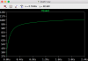
Using my model gives a vaguely approximate voltage build-up of the cap but is never going to give an accurate result, because the cap charging is assymptotic towards the target voltage.
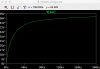
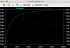
Here's an asc for a sim of your new battery model when discharging at 100A down to 320V. I've included a revised approximate SOC indicator which simply assumes 380V and 320V on the battery correspond to 100% and 0% charge respectively.
 

Attachments

  • Draft7.asc
    1.6 KB · Views: 202
Thank you, the discharging voltage is clearly displayed. Oh, I see.
But what about if I want only to see the charging sequence, and not the discharging curves, how would the asc-file be modified to display that? Okay, thats a good assumption, that 380 V is 100 % and 320 V is 0 %.
 
But what about if I want only to see the charging sequence, and not the discharging curves, how would the asc-file be modified to display that?
Just add a charge voltage source (say 390V, perhaps with a bit of series resistance), remove the 100A load (B2) and change the .ic directive to suit your starting (discharged) voltage, i.e to 320.
 
Last edited:
Thank you very much alec_t. You're explanation and assistant is really helpful. Just one last question regarding the battery,
If I understand this correctly, 108 V in the graph is corresponding to 320 V (100%) and 27 V is corresponding to 320 V (0 %) as we talked about before?
I just want to clarified if I am on the right track.

Ps. At the end, I want to connect the battery with the DC/DC converter as a voltage source, but it seems to be ripple? I know that the DC/DC converter is giving out pure and constant DC when its not connected to anything. Could you maybe please check that, if you have time? Cause I really do not know what the problem could be Ds.
 

Attachments

  • forum16.png
    forum16.png
    36.8 KB · Views: 234
Last edited:
but it seems to be ripple? I know that the DC/DC converter is giving out pure and constant DC when its not connected to anything.
As sooon as you draw load current there is bound to be ripple. The load current reduces C1 voltage, which takes time to recover by C1 being charged. Your converter can't provide infinite charge current and doesn't have an infinite operating frequency. The ripple is only ~220mV peak-to-peak sitting on 320VDC.
108 V in the graph is corresponding to 320 V (100%) and 27 V is corresponding to 320 V (0 %) as we talked about before?
Which graph?
 
Last edited:
As sooon as you draw load current there is bound to be ripple. The load current reduces C1 voltage, which takes time to recover by C1 being charged. Your converter can't provide infinite charge current and doesn't have an infinite operating frequency. The ripple is only ~220mV peak-to-peak sitting on 320VDC.

Which graph?

Oh, I see. So if the ripple is relative low, it would be acceptable to have I guess.


See the attached file.
 

Attachments

  • forum16.png
    forum16.png
    36.8 KB · Views: 237
But I notice that the SOC level looks strange while having the battery connected to the converter. Should it look like that?
I mean, it displays mV, but maybe I need to assume again, that 450mV is 100 % of SOC and 100 mV is 0% ? Correct me if I am not on the right track with this.
 

Attachments

  • forum17.png
    forum17.png
    44.7 KB · Views: 223
The SOC indication is only approximate. It starts at close to zero because 320V is arbitrarily defined as the zero point. If you simulate your converter circuit attached to the battery model the SOC will take ages to rise, because LTS is doing millions of calculations just to solve the equations relating to your converter. That's why it's best to simulate the battery model separate from the converter: you can use an entirely different time scale for the sim.
Incidentally, when your sim involves numbers as large as 300V, it's pointless worrying about a few mV or figures after the decimal point. A simulation is just that; not real life.
 
Oh, I see. But I notice that I made a misstake with the input voltage source to the battery. I wanted to have the voltage and current varied in order to simulate a charger, do you how to simulate a charger as a source for the battery? The characteristics should look something like the attached image when I am charging.
 

Attachments

  • lithium_charger.gif
    lithium_charger.gif
    4.2 KB · Views: 225
  • HV battery model.asc
    1.6 KB · Views: 195
That charge profile consists of a constant-current (CC) part followed by a constant-voltage (CV) part. Your charger circuit doesn't provide either a CC or a CV function. Is this an entirely separate sim you want to do?

Edit: In the asc file in post #30, just change the V1 voltage to, say, 380V. The battery will then charge from its initial 320V.
 
Last edited:
Yes, it is an entirely separate simulation I want to do. Just to see if the battery charging properly. Otherwise, I guess I could connect my DC/DC converter to the battery.

I updated the resistance and capacitor, it was wrong apparently, but now it is more correct.
 

Attachments

  • DC-DC+HVbattery.asc
    5.5 KB · Views: 192
Here's a CC/CV sim using your battery model. It switches from CC to CV when the battery voltage reaches 370V.
 

Attachments

  • CC&CV-charge.asc
    2.3 KB · Views: 204
Oh, Thank you very much. It looks great. So now I got a SOC value where 90V is 100 % SOC, and 0V is 0 % SOC.
And for the lithium Ion charging characteristics, the cell voltage and current looks similar to the graph.
So now the battery is charged properly.

I hope I can connect my DC/DC converter to the battery to see the similar graphs.
 

Attachments

  • SOC.png
    SOC.png
    34.1 KB · Views: 218
  • lithium Ion charging characteristics.png
    lithium Ion charging characteristics.png
    53.4 KB · Views: 247
So as you stated before, it is a bad idea to connect more circuits with each other. I have also notice it is too complicated to connect everything together. Cause I am trying to simulate an charger. So in that case, I would to simulate these separately.

- AC/DC converter + PFC
- DC/DC converter
- Battery (the load)

Do you think that is okay to do that?
Like I can assume that as soonest these circuits are working separately, I can have the assumption that these will working together if they are operating together.
 
Do you think that is okay to do that?
That's how I'd do it. Any simulation makes certain assumptions. Keep reminding yourself that a simulation is only an approximation of real life, albeit a sufficiently accurate approximation for many practical purposes.
 
Yes, thats so true, I will keep reminding myself about that.
However, I hope it is okay if can ask an another question regarding the AC/DC Converter with interleaved PFC. I am trying to simulate that circuit, but what I have understand I need to implement an IC circuit of the interleaved PFC, in order to simulate an interleaved PFC.

Since it is complex, is it possible to only use voltage sources as pulses connected to the MOSFETs instead to simulate an interleaved PFC?
I have attached my attempt to do it.

However, I am also trying to add EMI-filter after the AC input, but I am not sure how it should look like? Is it consisting of 2 inductors, and 4 capacitors? I am not sure. Some sources says it is including more than that. I have done that for my DC/DC converter, see the second attached file.

Truly thank you alec_t.
 

Attachments

  • OBC_ACDC_16A.asc
    5 KB · Views: 194
  • OBC_DCDC.asc
    5 KB · Views: 211
Last edited:
I am also trying to add EMI-filter after the AC input
I've not tried EMI filter design. Other members here should be able to advise though.
 
Oh, tats okay. alec_t, just one more question regarding error amp, how can I implement into my AC/DC circuit so I can get constant output voltage?
It should be between 300-400 V. I tried to play with my circuit, but it didn't work. I know I have asked a lot, but I will stop doing that from now on.
I have learned a lot anyway thanks by you.
 

Attachments

  • OBC_ACDC_16A.asc
    6.1 KB · Views: 208
I updated the file a bit, I wanted to simulate an 230 V AC grid source, so I guess I need to have 230 V (RMS) where the amplitude is about 325.269 V.
 

Attachments

  • OBC_ACDC_16A.asc
    6.9 KB · Views: 191
Status
Not open for further replies.

Latest threads

New Articles From Microcontroller Tips

Back
Top