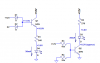
What I mean by expanding to all the outputs is this: output 0 should light LED's 0 & 1, output 1 should light 1 & 2, output 2 should light 2 & 3, etc. If another output was added to Ron H's driver section, you'd have another transistor with the base connected to Out1 & Out2 via resistors. The result would be that the bases of all the transistors would be connected in common, so a trigger to one would be a trigger to all. Hence the diodes are still needed to prevent that.