Continue to Site

Welcome to our site!

Electro Tech is an online community (with over 170,000 members) who enjoy talking about and building electronic circuits, projects and gadgets. To participate you need to register. Registration is free. Click here to register now.

  • Welcome to our site! Electro Tech is an online community (with over 170,000 members) who enjoy talking about and building electronic circuits, projects and gadgets. To participate you need to register. Registration is free. Click here to register now.

Light dependent resistor circuit

Status
Not open for further replies.

Discv

New Member
Hi, I'm new to your interesting forum- and a complete plank with electronics.
So I am looking for advice.
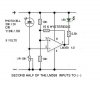
Hopefully I have managed to attach a circuit given to me.
Problem is- I think- that the LDR in the circuit is about 10 ohms [light] and 25k [dark]

All I can get hold of is [typically] 10k [light] and 0.1M [dark]

So I reckon that components need jiggering.

ANY help would be welcome.
 
Try changing the pot from 2k5 to 100k.
The circuit shown will trigger the 555 when the LDR goes dark. If you want triggering to occur when the LDR goes light just swap the LDR and pot positions.
 
Most LDRs have dark resistance in the 100M ohm region. 100K sounds more like twilight, not pitch black dark.
 
Thanks to both above. Could you advise as to a spec. that I should look for in selecting a LDR
 
Hi,

If you don't mind using a LM358 here is a circuit that I found on the net a few years ago.

And the application I made with it.
 

Attachments

  • PhotoCellSch.jpg
    PhotoCellSch.jpg
    35.3 KB · Views: 183
  • PhotoCellSch PEBBLE.jpg
    0 bytes · Views: 5
Last edited:
That is not a good schematic,w LDR connecting to pin 2. I have a better and simpler using 555. I will post it tomorrow.

Gajanan Phadte
 
For a not good schematic, it is working pretty darn well!

I was using it with a cheap laser pointer at 4 to 5 meter away while expirementing.

(Using a laser pointer could be dangerous for the eyes, humans or animals.)
 
Last edited:
I have many cheap solar garden lights. The parts in them are so cheap that they rust away within one year. The Ni-Cad battery cell and its holder, the on-off switch, the IC or transistors and the LED.

On a cheap solar garden light that still works after one year usually it is the LDR that fails. Maybe it gets sunburned or maybe moisture destroys it.
 
I'd think that moisture was the culprit considering all the morning dews, rainfall, high humidity, etc. Most LDRs you find are not hermetically sealed. Considering that the LDR has the greatest dynamic range of nearly any electronic component (100 ohms to over 100M ohms), it wouldn't take much to screw it up.
 
Guys, I am no nearer a solution to my original question. Which was- can anyone spec. a LDR and suggest alterations to my scheme that would be needed to employ that device.

Just for the record- I intend to use it to switch an electric fence energiser off during daylight hours. I only want to scare the foxes and not the grand kids! HV is provided with a 12v motor bike coil. The energiser is pulling 20ma in pause and 50ma under pulse conditions.
I am powering the set up with a 12v bike battery, charged by a small solar panel. The system being off during the day would also allow charging to catch up.

I also have to consider that here in London UK night is not as dark as many places.
 
Well, you did said "ANY help would be welcome".

The solution that I posted answered all your questions. It is adjustable and would probably work nicely for your project.

I just tested 2 LDR that I have and they are both working with this circuit.

The first one is going from 130 Ohms under my fluorescent lamp to 130K under my desk and the other one is going from 250 Ohms to 800K

The schematic circuit will give the action that you need, that is ON at night. Just change the LED resistor if you use it at 12 volts. The breadboard circuit gives the opposite. Pin 2 and 3 are swapped.

(On the picture, pin 1 of the chip is on top right.)
 
Last edited:
If there is NiCd, it will always corrode.
No.
All my solar garden lights use a Ni-Cad cell made in China.
Some rust away in less than one year. Others last for years.
I have two Chinese Ni-Cad cells that have been outside for 5 years and they have no rust. Today they will not hold a charge.

My Energizer Ni-MH cells have stainless steel cases and do not rust.
 
Talk is cheap!!

The biggest quality of the schematic that I posted is that... it is posted!

It is there for anybody to use it.

This guy reply stating that the schematic is no good without saying wy and not forfill (fulfill) is commitment to post his schematic is completely worthless.

Sorry, but I resent that!
 
The biggest quality of the schematic that I posted is that... it is posted!
It is there for anybody to use it.
Bonjore (Sorry, my French is terrible),
1) It is a fuzzy JPG file type instead of a very clear GIF or PNG file type.
2) It shows a solar cell connected backwards, not a light-dependent-resistor.
3) The resistor values for the opamp inputs are much too low.
4) It does not have an important supply bypass capacitor to keep the battery voltage from jumping all over the place.
 
Thanks AG. "Bonjour" would be better.:eek:

I suppose that you are talking about the original file (JPG). I took it on the web.

Would be more interesting if you gave us the values that you are thinking of. Personnaly, I am not an expert and I enjoy learning.

As it is, this circuit is working fine with a nice hysteresis. But I am sure that much better could be found.

But for now, obviously, not here in this thread, in JPG or in any other format.
 
Last edited:
Would be more interesting if you gave us the values that you are thinking of..
Look at the datasheet for the LM358 dual opamp. Its input bias current is typically almost nothing and its entire supply current is about as much as the two 10k input bias resistors. So the two 10k resistors can be 100k each.

The 10k variable resistor can be 100k for 10 times the sensitivity and the 15k hysteresis resistor can be 150k.
 
Status
Not open for further replies.

New Articles From Microcontroller Tips

Back
Top