Continue to Site

Welcome to our site!

Electro Tech is an online community (with over 170,000 members) who enjoy talking about and building electronic circuits, projects and gadgets. To participate you need to register. Registration is free. Click here to register now.

  • Welcome to our site! Electro Tech is an online community (with over 170,000 members) who enjoy talking about and building electronic circuits, projects and gadgets. To participate you need to register. Registration is free. Click here to register now.

Light dimmer circuit

gjoo

Member
In an older textbook it states that a lamp des not glow until about 50 percent of rated voltage, the controls are arranged to start functioning at 50 or 60 volts.

How are the controls changed, because it is suppose to differ from a universal motor speed controller, but both circuits look the same.
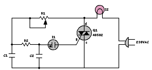
 
The circuit for the universal motor and lamp dimmer both look like this circuit, so how are the components in the circuit above adjusted to start at 50 volts?

Circuit Diagram:-

Lamp Dimmer Circuit Diagram
 
It depends on the properties of Q1, a 40502 Triac, and I1 a neon bulb. Do you have datasheets for these parts?
 
No, the book just vaguely touched on the subject. But, how would you adjust the circuit above to start working at 50 volts, which components would be adjusted or changed,?
 
I would start with the Gate voltage required for the TRIAC to conduct. Then I would want to know the holing current for the TRIAC. Next, I would want to know the voltage across the Neon Lamp when it illuminates. Then it should be possible to find values for the two capacitors, the resistor, and the potentiometer.
 
But, how does the potentiometer provide a range of 50-110 volts and not 0-120 range, in this the circuit above?
I'm guessing, the potentiometer R1 drops the input voltage from a peak of 230 to some lower value. This charges capacitor C1 and then R2 drops the voltage a bit more and charges C2. The neon bulb when it illuminates enable the gate and turns on the TRIAC.
 
Show me what you are talking about. Words are too imprecise.
 
if 50% of Vin starts with 50V that's about 25% which is closer to the truth for average power needed to reach 1000 'K dim in a bulb This is close to 90 deg. But since the bulb has 10:1 resistance change, it causes hysteresis SO start dim and reduce to dim are different thresholds. Thus you need to attenuate C1 with 27k shunt.
 

Latest threads

New Articles From Microcontroller Tips

Back
Top