Continue to Site

Welcome to our site!

Electro Tech is an online community (with over 170,000 members) who enjoy talking about and building electronic circuits, projects and gadgets. To participate you need to register. Registration is free. Click here to register now.

  • Welcome to our site! Electro Tech is an online community (with over 170,000 members) who enjoy talking about and building electronic circuits, projects and gadgets. To participate you need to register. Registration is free. Click here to register now.

Light activated circuit

Status
Not open for further replies.

fixit7

Member
While I am waiting for my pot to come in, I thought maybe this might work.

I have many of the components that it requires already.
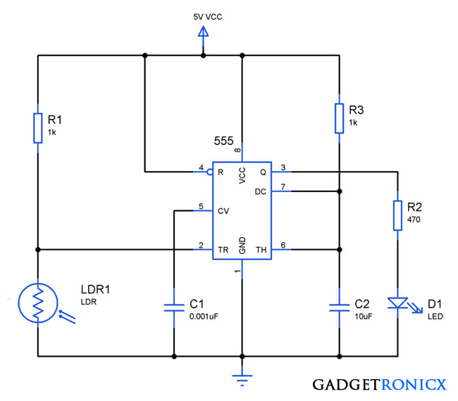

Could it be modified to set off a piezo buzzer in addition to the led?
 
A modification is not required. Simply connect a piezo beeper to its pin 3 and to the circuit ground.

I think the 1k resistor value is too low to feed the LDR. I would use 10k.
 
I did so. Nothing happened.

I am waiting on a 25K pot.
R1 must be 100k or more. You'll be lucky to get R1 down to about 12k and pin 2 must fall below Vdd/3 to trigger.

Good luck.
 
I have half of those already.

I may need an assortment of pots too. :)

If you don't have a 100k, try a 68k or 47k or 150k or 220k. Any might work, I just assumed you will have a 100k in your parts bin.
 
I am still fairly new but I am building up my parts bin.

I did order that assortment of resistors you recommended.

As I build up my stock, I will find myself having to order less.

So far I have ruined one bc547b and one 555 chip.

So when I get that pot and do get a circuit working, can I just see what the resistance is then use that value for the resistor in the final circuit?
 
Since the piezo beeper did not work them maybe it is a piezo speaker that needs an external oscillator instead of being a piezo beeper that already has an internal oscillator. A piezo beeper operates when it is powered from DC. A piezo speaker is powered from an amplifier driven with an audio signal.
 
My piezo buzzer still works.

PRODUCT TYPE
: PIEZO BUZZER
PRODUCT SERIES : DB-E78
DESCRIPTION : PZ BUZZER PULSE 12VDC L/W ABS

OPERATING VOLTAGE RANGE ( VDC ) 3 ~ 15
RATED VOLTAGE ( VDC ) 12
( mA ) 10
( dBA/ 30 cm ) 90
* MAX. RATED CURRENT
* MIN. SOUND OUTPUT
* FREQUENCY
( Hz )
TONE NATURE
PULSE
OPERATING TEMPERATURE
( o C )
TERMINAL
- 20 ~ +60
LEADWIRE
 
So far I have ruined one bc547b and one 555 chip.
That is called, "letting the magic smoke out". The only people who don't ruin parts are managers or someone even less valuable.
So when I get that pot and do get a circuit working, can I just see what the resistance is then use that value for the resistor in the final circuit?

Yes.
 
Your piezo buzzer is an OPERATING VOLTAGE RANGE ( VDC ) 3.0 ~ 28 and you have a 5 VDC circuit so don't expect much if any sound. Pin 3 the 555 out will out less than 5 VDC. I would just start simple, less the buzzer and see if you can get the LED going. Look at the voltage on pin 2 of the 555 (trigger) and keep in mind what gophert has pointed out:
You'll be lucky to get R1 down to about 12k and pin 2 must fall below Vdd/3 to trigger.
Unless you get pin 2 below 5/3 = 1.667 volts nothing will happen.

Ron
 
Check the sig line from JimB:
"Experience is directly proportional to the value of the equipment ruined. "

There's also another good one I have seen, something along the lines of:
"Experience comes in the form of a flash, a bang, and a shower of sparks!"

Point is, if you aren't accidentally blowing stuff up and then discovering why it happened, you aren't really trying. Anyone can play it safe and build tutorial kits produced by someone else, or stick rigidly to plans made available on the interwebs, but apart from soldering practice and component ID, how much is learned from that? Experimentation is where some of the more valuable lessons are learned. When you are down to your last xyz chip, transistor, uC etc. and the next order won't come in for a few more days, you are going to double and triple check before applying the power. Datasheets are your friend in practically every case.

An analogy as a final note:
Practically all competitive racing drivers will end up involved in a crash at some point. The less successful ones wonder why they crashed, but the most successful ones know exactly why they crashed...
 
The circuit schmatic shows R1 and R2.

I am only using R2 because the author said R1 is often not necessary.

I wonder if lack of R1 is the problem?
 
The schematic wrongly shows 5V so we are talking about the problems of using 5V but he is using 9V, not 5V.
The schematic does not show a pot but he talks about getting a pot. Where will it be used?
 
The circuit schmatic shows R1 and R2.

I am only using R2 because the author said R1 is often not necessary.

I wonder if lack of R1 is the problem?
The schematic does not show an R2. It shows only R1 as 1k ohms which is much too low.
 

Attachments

  • LDR and 555 circuit.png
    LDR and 555 circuit.png
    38.2 KB · Views: 142
Sorry about the mixup.

This is what I made.

With no laser, led lights up.

With laser, led goes off.

Since my piezo buzzer did not work, what else can I use to make a sound?

118300
 
Last edited:
As drawn the LED is backwards. When pin 3 is low nothing will happen and when pin 3 is high nothing will happen. Why are you taking the out and routing the out (pin 3) back to the trigger (pin 2)? Note I said "as drawn" the LED is backwards.

Take your LDR and just place it on the bench. Measure the light and dark resistance and note what they are. Learn how to use a transistor on the output of the 555 for increased current loads.

Ron
 
Status
Not open for further replies.

Latest threads

New Articles From Microcontroller Tips

Back
Top