Electro Tech is an online community (with over 170,000 members) who enjoy talking about and building electronic circuits, projects and gadgets. To participate you need to register. Registration is free. Click here to register now.
Welcome to our site! Electro Tech is an online community (with over 170,000 members) who enjoy talking about and building electronic circuits, projects and gadgets. To participate you need to register. Registration is free. Click here to register now.
The beep rate might just be a function of the voltage applied to the beeper. Try a few till you find something you like or just place a resistor in series with the beeper.
"It beeps with a much higher rate". What is rate?
A piezo beeper has a continuous oscillation: Beeeeeeeeep. Does yours have a discontinuous beep rate: Beep, beep, beep etc?
The frequency of the oscillator in a piezo beeper is set by the acoustic resonance of the piezo disc in the cavity it is in so that its beeping is the loudest.
Please post the schematic of your final working circuit with the 555 connected as a 5 minutes timer. The other schematics you posted do not work properly.
The photo does not show the schematic, instead it shows a photo of an intermittent solderless breadboard with messy wires all over the place.
None of the parts or wires are labelled.
The wiring of the pot is not shown.
One of the key players in this game is the LDR which in this case looks to be a CDS Photocell. Matter of fact based on your image it looks to be very similar to this photocell. Knowing the Light and Dark resistances is sort of important which is why I asked about those numbers in an earlier post. There are hundreds of photocells out there and knowing what you have makes it a heck of a lot easier to help. The Internet is hardly a reliable place to find good functioning circuits, some work fine, some almost work and some never will.
Personally I see the 555 timer as a poor choice for a light/dark detector but obviously it is what you have and decided to run with. You started by mentioning breaking a LASER beam and when I questioned that and gave you a few links it became I just want it to work the way it is. Your first drawings reflected parts installed backwards. If you don't plan to learn and understand data sheets all of this becomes a fruitless exercise in futility which is why most of the early members who wished to help bailed out. To help someone people need a feel for where they are, what level they understand. You have no interest in learning or starting in the shallow end of the pool so just ask by saying I need a light dark sensor circuit. This is not something I wish to pursue. I would have just suggested you buy one of these from Ebay or Amazon for a few bucks and been done with it.
It works, be happy and life is good. I am sure armed with Google you will find other forums and hopefully with more helpful and maybe even Most Helpful members. Just point out you aren't interested in learning, you just want instant results.
I do not use a Circuit Diagram Program. Instead I simply copy and paste parts together to make a schematic with Microsoft Paint Program.
Most schematics are already on a datasheet (the 555 timer circuit) or are already posted somewhere. Simply copy and paste it.
Gimp is good as are several other free photo shop programs. There are also other countless free software programs out there designed for doing electrical circuits. Granted some have a steeper learning curve than others but some are really pretty easy to learn. While I haven't a clue where you plan to go with electronics but even at a hobby level it doesn't hurt to learn some new software. Obviously your choice. The circuit you have works so I guess you have what you wanted or needed. Have a good one.
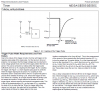
Here is a better circuit that triggers when your laser beam is broken. Whether it stays on for 5 minutes depends on the quality of your 1000 uF capacitor - yo need one with low leakage or you mA need to increase the resistance of the 270k to 330k or more.
The "test switch" allows you to trigger as you want.
Cancel button turns of the LED immediately.
Gophert, your timer will not timeout if something blocks the LED (a parked truck?) for time longer than the timeout.
The original circuit has the same problem.
Gimp is good as are several other free photo shop programs. There are also other countless free software programs out there designed for doing electrical circuits. Granted some have a steeper learning curve than others but some are really pretty easy to learn. While I haven't a clue where you plan to go with electronics but even at a hobby level it doesn't hurt to learn some new software. Obviously your choice. The circuit you have works so I guess you have what you wanted or needed. Have a good one.
Here is a better circuit that triggers when your laser beam is broken. Whether it stays on for 5 minutes depends on the quality of your 1000 uF capacitor - yo need one with low leakage or you mA need to increase the resistance of the 270k to 330k or more.
The "test switch" allows you to trigger as you want.
Cancel button turns of the LED immediately.
Both switches are momentary but you can definitely use toggle switches - just flip and flip back.
Also, low leakage are not "Required", they will just help get the "actual" on time close to the "theoretical" time from the published calculation for 555 timers. I would just use any 1000uF and adjust the resistor.
This site uses cookies to help personalise content, tailor your experience and to keep you logged in if you register.
By continuing to use this site, you are consenting to our use of cookies.

")