cesco
New Member
Hi everybody, I'm new here and I think this is the right place to post some questions about a home made circuit for a Leslie (i.e. rotary speaker) simulator I'm going to build.
The project is form a 1971 issue of "Popular Electronics". The schematics can be found **broken link removed**.
Here are the questions:
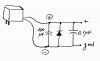
1) I live in Italy, so I have 220V ac coming out from the electrical grid. How can I modify the transformer/rectifier stage to adapt it to 220V? Or, even better, to allow it to be powered by one (or two) 9V batteries?
1a) Are you able to gather from the schematics what is the voltage at the + end of the rectifier? The problem is to pass from 9V to that voltage. Am I right?
2) The circuit can be bypassed with a footswich connected to J3, using a lamp coupled to a photoresistor (I1\LDR1). I already done that at a hardware hacking lab, with a small photoresistor (5mm of diameters, I don't actually know ohm ranges) and a small LED (again, I can't be more precise) taped together with electrical tape. Are them sufficient, or do I need the precise components pointed out in the schematics? I'm not able to figure out what exactly is a "#46 incandescent panel lamp" and probably the CL703L could be difficult to find.
3) The website in which I found the schematics suggests to use some 2SC1213 transistors for Q1,Q3 and Q4, a MPF102 transistor for Q2 and a 1N5232 zener diode for D1.
All these components are cheap and easy to find, in your opinion are they worth trying?
Thanks a lot in advance for help!
Cesco
The project is form a 1971 issue of "Popular Electronics". The schematics can be found **broken link removed**.
Here are the questions:
1) I live in Italy, so I have 220V ac coming out from the electrical grid. How can I modify the transformer/rectifier stage to adapt it to 220V? Or, even better, to allow it to be powered by one (or two) 9V batteries?
1a) Are you able to gather from the schematics what is the voltage at the + end of the rectifier? The problem is to pass from 9V to that voltage. Am I right?
2) The circuit can be bypassed with a footswich connected to J3, using a lamp coupled to a photoresistor (I1\LDR1). I already done that at a hardware hacking lab, with a small photoresistor (5mm of diameters, I don't actually know ohm ranges) and a small LED (again, I can't be more precise) taped together with electrical tape. Are them sufficient, or do I need the precise components pointed out in the schematics? I'm not able to figure out what exactly is a "#46 incandescent panel lamp" and probably the CL703L could be difficult to find.
3) The website in which I found the schematics suggests to use some 2SC1213 transistors for Q1,Q3 and Q4, a MPF102 transistor for Q2 and a 1N5232 zener diode for D1.
All these components are cheap and easy to find, in your opinion are they worth trying?
Thanks a lot in advance for help!
Cesco