darkenreaper57
New Member
I will begin by saying that I am new to these boards and still a beginner when it comes to electronics  .
.
Anyway, I built a fan controller a while back, but I finally put it into practice for long duration overnight.
Basically, I use 3 LM317 circuits to run 3 120mm fans. Two of the LM317 chips are run in parallel, however, to a single potentiometer. The other LM317 circuit (it is on the same board, but logically separate from the other two) uses its own potentiometer.
The schematics are located here. I only made the minor modification of hooking 2 circuits to 1 pot , for aethetic purposes - I wanted 2 knobs, not 3. **broken link removed** -
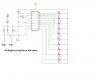
I also hooked up 2 LM3914 voltage monitor circuits - one per potentiometer. Here are the schematics **broken link removed**
Now, I woke up this morning to check things out. I've been running the fans at around 6V, and they were still fine. The LED's on both meters showed 6 bars (as they should).
When I turned up the knobs to max voltage (around 10V), I noticed something. The LED's on the meter hooked up to the LM317 circuit in parallel all lit up, but the ones hooked up to the single one did not. 2 or 3 were unlit.
I have a hunch that they will light up again after I unplug the fan controller and let it sit. Hopefully they did not burn out. Sorry for the lack of a complete diagram - I'll made one if needed.
Basically I want to know if this is due to applying too much voltage (and thus too much current) to the LED's, and if so, how to fix it (resistors, I assume?).
Thanks for any help, and I'll clarify things if necessary.
EDIT: As expected, all of the LED's except the very top one are now lighting up. Argh, I hope I don't need to go back to the drawing board...
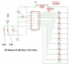
EDIT 2: Also, as expected, the 9th LED is beginning to flicker (10th is off). I also remeber another modification I did to the LM3914 circuit: In place of the 680 ohm resistor, I put a 5.6k and 1k in parallel to yield about 850 ohms. I did this so the meter would light up completely at 10V instead of 12, as my fan controller can only go up to 10.5V or so.
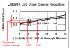
This wouldn't change the current through the LEDs though, right? According to the datasheet, R1 in the casemods.com diagram determines current, and I used the same 1.2k resistor. Current is just over 10 mA.
I suppose I could always crank out my multimeter and read the current, but that would mean unsoldering and possibly screwing something up (and a hassle).
Argh. Hopefully someone here knows what is going on.
EDIT 3: Yep, they aren't burnt out. I went to class and turned it all of, and just fired everything back on. All of the LED's are lit up.
.Anyway, I built a fan controller a while back, but I finally put it into practice for long duration overnight.
Basically, I use 3 LM317 circuits to run 3 120mm fans. Two of the LM317 chips are run in parallel, however, to a single potentiometer. The other LM317 circuit (it is on the same board, but logically separate from the other two) uses its own potentiometer.
The schematics are located here. I only made the minor modification of hooking 2 circuits to 1 pot , for aethetic purposes - I wanted 2 knobs, not 3. **broken link removed** -
I also hooked up 2 LM3914 voltage monitor circuits - one per potentiometer. Here are the schematics **broken link removed**
Now, I woke up this morning to check things out. I've been running the fans at around 6V, and they were still fine. The LED's on both meters showed 6 bars (as they should).
When I turned up the knobs to max voltage (around 10V), I noticed something. The LED's on the meter hooked up to the LM317 circuit in parallel all lit up, but the ones hooked up to the single one did not. 2 or 3 were unlit.
I have a hunch that they will light up again after I unplug the fan controller and let it sit. Hopefully they did not burn out. Sorry for the lack of a complete diagram - I'll made one if needed.
Basically I want to know if this is due to applying too much voltage (and thus too much current) to the LED's, and if so, how to fix it (resistors, I assume?).
Thanks for any help, and I'll clarify things if necessary.
EDIT: As expected, all of the LED's except the very top one are now lighting up. Argh, I hope I don't need to go back to the drawing board...
EDIT 2: Also, as expected, the 9th LED is beginning to flicker (10th is off). I also remeber another modification I did to the LM3914 circuit: In place of the 680 ohm resistor, I put a 5.6k and 1k in parallel to yield about 850 ohms. I did this so the meter would light up completely at 10V instead of 12, as my fan controller can only go up to 10.5V or so.
This wouldn't change the current through the LEDs though, right? According to the datasheet, R1 in the casemods.com diagram determines current, and I used the same 1.2k resistor. Current is just over 10 mA.
I suppose I could always crank out my multimeter and read the current, but that would mean unsoldering and possibly screwing something up (and a hassle).
Argh. Hopefully someone here knows what is going on.
EDIT 3: Yep, they aren't burnt out. I went to class and turned it all of, and just fired everything back on. All of the LED's are lit up.