Continue to Site

Welcome to our site!

Electro Tech is an online community (with over 170,000 members) who enjoy talking about and building electronic circuits, projects and gadgets. To participate you need to register. Registration is free. Click here to register now.

  • Welcome to our site! Electro Tech is an online community (with over 170,000 members) who enjoy talking about and building electronic circuits, projects and gadgets. To participate you need to register. Registration is free. Click here to register now.

Led

Status
Not open for further replies.

AtomSoft

Well-Known Member
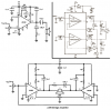
I made this pre/mini amp i believe to be 1-2W not sure. Anyway i wanted to know how would i connect a LED to it to detrmine if on ( of course i will install a switch first). Would like it to be a small led(red) i have so it wont eat to much power.

Below is my pre/mini amp
**broken link removed**
 
LM 386.PNGIf you do not have a potentiometer on the input, add a 47K resistor from input to V-. This will keep noise down and prevent the input from floating DC.

Add the snubber networks. They add stability/prevent oscillation. Instead of 2 snubbers, you can use a single snubber from one output directly to the other output. Just use a .022uF and a 20 Ohm resistor instead of the values shown above.

The data sheet does not mention if the IC has internal current limiting. You may have to experiment with different higher than 8 ohm speaker impedances in order to find optimum power output. There may not be an advantage to running a bridged amplifier if the IC cannot deliver the current and power necessary.

Edit: Oh, I forgot the LED
 
Last edited:
AtomSoft said:
LOL this works fine i just wanted led which i made already with 2 Diodes and a resistor and LED

Without the snubber you run the risk of the LM386 oscillating. When it does that it will heat up and die. It might not do it now but you have no guarantee that it won't, especially if you stick longer speaker wires on it.

I would have thought you only needed one resistor and the LED. What did you use the other two diodes for?


Torben
 
for fun and learning also bored. Ok for the snubber:

Just use a .022uF and a 20 Ohm resister but where?

From the + and - of input ? Capacitor on which side ? before or after resistor or it doesnt matter ?
 
AtomSoft said:
for fun and learning also bored.

:) I meant what purpose did you put them to?

Ok for the snubber:

Just use a .022uF and a 20 Ohm resister but where?

From the + and - of input ? Capacitor on which side ? before or after resistor or it doesnt matter ?

As Bob said, just put them between the outputs--so put the resistor and cap in series between the lines to the speakers. You can see a schematic example in the bottom schematic at: http://runoffgroove.com/littlegem.html (check the schematic for the Little Gem MkII).


Torben
 
Well i dont have a .22 and they dont sell it around here. So can i use like a .022 or or a .1uf capacitor? Resistor is 10k in pic should i put it to a 20 ohm or ???
 
The datasheet shows a 0.05uF capacitor and a 10 ohms resistor.
Not 0.22uF and not 0.022uF capacitor.
Not a 10k ohms resistor and not a 20 ohms resistor.

The LM386s will become hot when they operate at continuous full power into an 8 ohms speaker with a 9V supply. The full power at clipping is 0.6W. The heating in each IC is 0.8W.

The Little Gem Mk2 bridged amplifier has a 4 ohm speaker so its output power will be very low and its heating will be very high.

Connect an LED in series with a current-limiting resistor from +9V to 0V.
 
audioguru said:
The datasheet shows a 0.05uF capacitor and a 10 ohms resistor.
Not 0.22uF and not 0.022uF capacitor.
Not a 10k ohms resistor and not a 20 ohms resistor.

In the bridged version, the two snubbers are effectively in series, so if you use a single snubber between the two outputs (not connected to ground) you can halve the capacitance and double the resistance.

Two .05 caps in series = .025. Use closest value: .022.
Two 10 ohm resistors in series = 20 ohm.

Am I wrong?
 
Last edited:
i got 2 LM386N-1's with NO GAIN. And im sure the datasheet isnt set in stone. I love electronics and im just learning but sometimes you have to make it your own am i right?

I left this puppy on for hours so far no issue at all everything cool tot he touch.It depends on the application to determine capacitance and resistance. And no where in the data sheet do i see 2 lm386 bridged. So as far as the .05uf it doesn't matter to me . I thank you for your advice but why am i going to change around a perfectly good working thing? I hear around you know a lot and maybe ill go buy some more lm386's since they're so cheap and try it your way but for now since most is soldered on board already, i am gonna stick with just adding the cap & resistor and hope for the best.

This will be used to just amp out a tv with a broken speaker . I just needed enough power to hear the dam thing lol . LED is already in place in series with a resistor. No problems with it also. Thanks again.

I will surely take all advice heard/read into thought.
 
It is usually best to follow the advice of the IC manufacturer. If they recommend a snubber circuit then use one.

The LM390 is nearly the same as the LM386 except it has bootstrapping for more output power and has a larger case.
It is shown bridged with a snubber between its outputs that has the same values as a single amplifier.

The TDA2005 is a bridged much higher power amplifier for cars. It has a separate snubber circuit at each of its outputs to ground.
 

Attachments

  • LM390.PNG
    LM390.PNG
    37.7 KB · Views: 142
I tried the Resistor and a capacitor and its a no go no sound but when i do it with out it ; its fine. What could be the problem ? cap? anyway ill leave it as is as not to over complicate something that seems simple (it works) why fix something that works. Even if it burns out in 2 days . At least it was alive for some time. :D
 
AtomSoft said:
I tried the Resistor and a capacitor and its a no go no sound but when i do it with out it ; its fine. What could be the problem ?

You did something wrong - as simple as that.

BTW, this talk of 'snubber networks' is highly confusing?, it's correctly called a 'zobel network' - and as suggested, it's pretty essential! (and fool proof).
 
Nigel Goodwin said:
You did something wrong - as simple as that.

BTW, this talk of 'snubber networks' is highly confusing?, it's correctly called a 'zobel network' - and as suggested, it's pretty essential! (and fool proof).

Yeah, I just re-read the thread where audioguru pointed that out to me. I get them mixed up anyway because they look similar (or flat-out the same).

Is this correct (if oversimplified): Snubbers are for transients and back EMF; Zobel networks are for preventing oscillations at high frequencies in audio circuits (at least 386s) and for frequency response flattening in crossovers?


Torben
 
ok i installed the snubber/zobel what ever you guys officially called it. The issue was bad resistor. I used a 22ohm instead since i have no more 20. Also i used a 0.022uF Polyester-film capacitor
 
Torben said:
Zobel networks are for .... frequency response flattening in crossovers?
Zobel circuits are used in speaker crossovers to flatten the impedance that the crossover network feeds, because a woofer is an inductor and its impedance rises at high frequencies. A tweeter has a resonant frequency where its impedance is too high for a crossover network.

Without a zobel circuit in a crossover then the crossover frequency and phase will be wrong and the increased Q of the LC tuned circuits might cause a peak.
 
Status
Not open for further replies.

Latest threads

New Articles From Microcontroller Tips

Back
Top