Continue to Site

Welcome to our site!

Electro Tech is an online community (with over 170,000 members) who enjoy talking about and building electronic circuits, projects and gadgets. To participate you need to register. Registration is free. Click here to register now.

  • Welcome to our site! Electro Tech is an online community (with over 170,000 members) who enjoy talking about and building electronic circuits, projects and gadgets. To participate you need to register. Registration is free. Click here to register now.

LED Strip lights (2 Amps) Short Fade on / Fade Off effect

Status
Not open for further replies.

ThomsCircuit

Well-Known Member
Id like to adapt this circuit to support more than 1 LED. I want to use this with a strip of LEDs i have. The strip is 15 feet. has 300 2835 leds. Draws about 2 amps @ 12v
The circuit should fade the leds from 0 to max current when turned on and max to 0 when turned off. the fade duration should be 2 seconds. From what I understand the fade duration is controlled by the capacitor when turned on and then R1 and R2 work with the cap to slow the drain when turned off. What I dont get is the author states that if R2 was omitted the fade off would take much longer. Less resistance (1K) = slower drain. Seems that less resistance would mean a faster drain. I know that question will get me in a lot of trouble (LOL) because my ability to grasps formulas is not as good as i wish they were but my curiosity will have to deal with it.

The author also explains that by changing R12 & C1 will affect the fade duration but what about adjusting for the load on the circuit? Here the circuit is only controlling a fed leds. What would i need to alter for my needs? 150 - 300 leds?

Thank you in advance.
T.B.
LEDfader_schematics.png
 
A transistor that can handle 2A and probably a Darlington to increase the gain.

Mike.
 
You might want to consider using a little Arduino or similar with an inbuilt PWM to create your fade and using a suitable power mosfet to handle the load without excessive heat.
The micro will allow you to easily vary the time period of the fade up and down and also act as an on / off timer, we use this method on our led strips.
 
Fade Schematic.
Where to place Darlington transistor in this circuit.
I can get TP120
Emitter- Base Voltage VEBO: 5 V
Collector- Base Voltage VCBO: 60 V
Maximum DC Collector Current: 5 A

From what i have read i think Q3 replaces Q1 but if you could tell me if that is correct or where i need to put it into the circuit.
I also need guidance on which transistor to use if what i have will not work and did I place the strip of LEDS in the right place?
Fade01.png
 
Last edited:
Ive done some reading about transistors.
In a previous post i learned that transistors can add a boost of power. I was able to increase a small 12v buzzers volume by adding a 547. Im sure the technical term "boost of power" is an insult to an engineer but thats how it appears to me.

In this project i need a more powerful transistor. 2 amps is draw of the reel of leds so a BJT or Mosfet are the best options. From what i read there are other circumstances to consider. Besides current I should look into power dissipation. I just want to be sure im getting the correct rated transistor for this project. I do appreciate the help.
 
On second thoughts, PWM is a much better solution. A Darlington will get very hot during the fade and will need a very big heatsink. As you know programming use a nano available for ~US$3. I recently bought some with USB C sockets.

Mike.
 
On second thoughts, PWM is a much better solution. A Darlington will get very hot during the fade and will need a very big heatsink. As you know programming use a nano available for ~US$3. I recently bought some with USB C sockets.

Mike.
I dont mind the heat sink. Just do not want to do adrino
 
Last edited:
Ive looked at other user powering a few meters of strip lights and they are suggesting an N-Channel Mosfet. Rated 6amps @ 20 volts.
Now what i find are mosfets available with ratings and prices all over the charts. Finding one with the specs i need is not possible but im told thats its ok if the ratings are higher.
IRF540 33A 100V
IRF740 10A 400V
IRFZ44 49A 55V
IRF3710 57A 100V
These are just a few that i can acquire and while the ratings are all over the place so are the prices.
My goal for this project is to place it in line between the led strip and the power supply.
Again i need help with selecting the correct components to power the strip and produce a 2 second fade during power on and power off. Fade On/Fade OFF

thank you
T.B.
 
Mosfets are more suited to PWM switching. To use a Mosfet (in analogue circuit) needs it to operate in the linear zone where it wastes a lot of power. Consider the power dissipated at half brightness, about 6W (6V at 1A???). A TIP120 (assume TP120 was typo) will get very hot dissipating 6W. A mosfet using PWM is either fully on or fully off so not dissipating much heat at all.

Mike.
 
Alright Ill have to let this project go for now. I do feel it can be done without coding. Just need to find the right combination of components. I did however learn something new about transistors and to me that's really why im on this board. Its not the success or failure of the project but what knowledge has been gained in the process. Thank you to everyone who has provided insight and shared their thoughts and ideas with me. You are greatly appreciated.

T.B.
 
Last edited:
Alright Ill have to let this project go for now. I do feel it can be done without coding. Just need to find the right combination of components. I did however learn something new about transistors and to me that's really why im on this board. Its not the success or failure of the project but what knowledge has been gained in the process. Thank you to everyone who has provided insight and shared their thoughts and ideas with me. You are greatly appreciated.

T.B.

It can be done without coding, but it's LOT simpler and more efficient using coding - and you probably don't need to do any coding anyway, as it's pretty likely that there's fading LED examples for Arduino already out there to download.

Just google for "arduino fading led"
 
It can be done without coding, but it's LOT simpler and more efficient using coding - and you probably don't need to do any coding anyway, as it's pretty likely that there's fading LED examples for Arduino already out there to download.

Just google for "arduino fading led"
If it can be done without coding then please offer a solution.
Ive learned a great deal over the past two years. Ive downloaded a few books on ohms law and the 555 IC and my father gave me his paperback tutorials on electronics from decades ago. I mention this cause I do not want you or the group to feel that I am taking advantage of your generosity.

I know that an N Channel Mosfet is a good choice. Ive seen this in many examples where there is a need to control high current. I understand that the majority of the heat generated from the transistor is due to the fade effect.
Ive learned that led strips are current driven and the bigger the cap the longer the fade duration.
II've made a great deal of circuits with the help of this group. Many were for me not easy but ive got no problem with difficult. So ill provide the details of the strip light and if you could help me with a component driven solution.
Led strip light:
300 leds
2 amps
12 volts

Thank you,
T.B.
 
Hello TC

I agree with the other members and the use of PWM LED drive, but if you really want to build a circuit using BJTs, and experience how it performs, you can do that. You'll find the power transistor(s) will get hot. Meanwhile, you should read about PWM and how it works. Then you'll understand why most are suggesting its use.

Meanwhile, here is a fade-on fade-off circuit you can experiment with. I don't really know if works since I haven't bread boarded it.
It seems to work in simulation though. R2 adjusts the amount of "fade".

1639721152641.png
 
Note, if you try using a MOSFET it won't work as the gate will charge and discharge too quickly so it'll be on or off. eTech's solution is using the transistor in it's linear range so it will get very hot.

Mike.
 
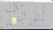
This is discrete component PWM fader, mainly just as a proof of concept.
It would need a suitable higher powered FET or darlington and correct LED current limiting (if the LED module does not include it).
The PWM frequency is also set far too low, just so the change in duty cycle is visible in the simulation; C1 should be 0.1uF or lower to eliminate flicker.

The basic PWM action works by comparing the control voltage on C3 to the charge / discharge [approximate] sawtooth on the 555 timing cap, using an LM311 (same pinout, different part number) to control the output transistor.

C3 is charged or discharged via R3, depending if the control switch is on or off; V2 emulates a switch to 12V to control the simulation.

The resistor chain and diodes in the middle restrict the voltage range on C3 to not too much more than the 555 trigger and threshold, to avoid excess dead times before the fade effect happens at switch on or off.

The red waveform is the control switch, blue the ramp on C3 and green the transistor collector.

PWM_Fader.png
 

Attachments

  • Fader.asc
    3.5 KB · Views: 230
R2 adjusts the amount of "fade".
Thank you. I will look into using PWM.
What are the values of R2 and R1
I cannot get TIP121 (supplier has only 1 TIP120) but I see a comparable part is TIP122. The voltage is higher. I think that means the additional voltage in 122 will burn even hotter than the tip121

Something about adrino that I could not figure out. When I wrote code I could create an installation program so the user could use what I created without the need to have the platform I designed it in. With adrino I assumed it worked the same way. I create a chain of events then burn them to a chip. That chip is removed from the adruino and placed in the circuit board. I can not find however any documentation to say it does work like this. It appears that you burn the data to the adrunio unit and run the program from the adrunio unit. I dont see how you "detach" what you created and apply it to your circuit without the adrunio being part of the project.
 
Last edited:
This is discrete component PWM fader, mainly just as a proof of concept.
Thank you for this and the explanation of how it functions..
I'd like to build this. THere are a few parts and the switchs (1&2) that I dont understand.
V1: thats power but then there's V2 and now I'm lost. Why 2 powers??
Switch 1 & 2: I don't understand why 2 switches.
RH111: is this the LM311 you are referring to? I cannot locate a part RH111. I dont see how it could be lm311 but that part of the schematic is unclear how its connected to the circuit. ( writing too small)
 
As I mentioned in the comments, the V2 power is emulating the control switch, for the simulation - ignore than and connect a real switch between the switch1 and switch2 points.

The RH111 is a comparator included in LTSpice; it's identical pinout and function to the LM111/211/311 devices.
Different manufacturer, different prefix, like LM555, NE555 etc.

If you click on the image then click again, it should zoom in so the text is clear.
Here is another copy anyway; just the schematic part:

PWM_Fader_Large.png

Just realised that RH111 only has labels, not pin numbers...
G = 1
IN+ = 2
IN- = 4
Power - (ground) = 4
Balance = 5 (no connection)
Bal/Strobe = 6 (no connection)
Out = 7
Power + = 8

You could use any other similar comparator in that location.


Note the LM311 data includes the 111 and 211 versions; the 111 is something like a military or aerospace quality version, the 311 the general consumer version.
 
Status
Not open for further replies.

Latest threads

New Articles From Microcontroller Tips

Back
Top