Turbo_Boss
New Member
Hello Guys,
I really apreciated if any of you can give me a schematic of a circuit project of a LED Position Indicator.
Let me explain what I need. I am going to intall a potentiometer on top of a servo that will have a arm that travel 90º
I need that this circuilt work with 12V to 14V and that it will turn only one led showing me if the arm is at 0º then if the arm move to 10º then it will turn off the led at 0º and it will only lite the LED at 10º then if the servo arm move to 40º it will turn off the LED at 10ºand it will lite the LED telling me that the arm is at 40º
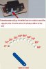
I will do a panel that will include 10 leds and I will put a label on top of each LED starting with 0º 10º 20º 30º 40º 50º 60º 70º 80º 90º
I have been looking on the web for circuit projects with LM3914 but all the projects that I find are volmeter, termometers, RPMs using 10 led segment but I dont find any one that work as a Position Indicator.
I dont know how to design electronic circuits but I know how to follow a diagram.
I reaaly apreciated if you can helpme giving me a schematic of this circuit and the value of the pontentiometer I need to intall over the servo arm.
I am including here a photo of the way I will arrange the LED on the panel so you have a better idea of what I need.
Thank You for your time and help,
Isaac
I really apreciated if any of you can give me a schematic of a circuit project of a LED Position Indicator.
Let me explain what I need. I am going to intall a potentiometer on top of a servo that will have a arm that travel 90º
I need that this circuilt work with 12V to 14V and that it will turn only one led showing me if the arm is at 0º then if the arm move to 10º then it will turn off the led at 0º and it will only lite the LED at 10º then if the servo arm move to 40º it will turn off the LED at 10ºand it will lite the LED telling me that the arm is at 40º
I will do a panel that will include 10 leds and I will put a label on top of each LED starting with 0º 10º 20º 30º 40º 50º 60º 70º 80º 90º
I have been looking on the web for circuit projects with LM3914 but all the projects that I find are volmeter, termometers, RPMs using 10 led segment but I dont find any one that work as a Position Indicator.
I dont know how to design electronic circuits but I know how to follow a diagram.
I reaaly apreciated if you can helpme giving me a schematic of this circuit and the value of the pontentiometer I need to intall over the servo arm.
I am including here a photo of the way I will arrange the LED on the panel so you have a better idea of what I need.
Thank You for your time and help,
Isaac