Continue to Site

Welcome to our site!

Electro Tech is an online community (with over 170,000 members) who enjoy talking about and building electronic circuits, projects and gadgets. To participate you need to register. Registration is free. Click here to register now.

  • Welcome to our site! Electro Tech is an online community (with over 170,000 members) who enjoy talking about and building electronic circuits, projects and gadgets. To participate you need to register. Registration is free. Click here to register now.

LED Numeric readout for grounded circuits

Status
Not open for further replies.
Clearly i have not described it properly.

I will describe the action as i see it,
bearing in mind i am not familiar with the
driver board that you have there.
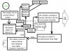
*******

plug in,
fire up test rig,
counter starts to count round, (this can be fast)
A fault to earth is met,
count stops,
last count displayed.

time passes, user notes down number,
user presses button to continue test,
counter continues,
If another fault is met,
count stops,
last count displayed.

time passes, user notes down another number,
user presses button to continue test,
no other faults met,
count gets back to the first one,
count stops,
first number is displayed again.

time passes, user sees first number again,
user knows a full cycle has been done.

Time passes just means a few seconds
till the button is pressed.

*************

I hope ive described it better this time,
You dont have to keep pressing the button.

John

************
************

Ive just seen that you would also like the unit
to run through a test to operate all the transistors
in turn.

That would be an extra function,
you would have to choose to make it do that,
probably with a rotary knob,

no not a knob, theres too many wires ...

how about moving the plug ?
to do that bit ?

John
 
Hi Dragster,

So you're checking for earth faults on the BASE of
these output transistors ?

And if they check out OK then you want to drive
each of them in turn,
to see that they operate the 'solenoids'

I'm sorry if i seem a bit slow to grasp this,
but have i got it now?

So would the first part be done with no supply to
the board, and the second part with the supply on ?

Regards, John
 
Hi Dragster,

I was looking for stuff on pinball
machines, and i found this.
Is this the sort of thing you mean?

**broken link removed**

I couldnt find a good picture of the
solenoid board driver section.

Regards, John
 
Hi John. Its funny you found the Marvin Web Page. It is created by a friend of mine. If you click the link and go down to the place to get boards repaired you will find me at top of the list.

**broken link removed**

If you want a picture of the solenoid schematic i will try to get you one.


I took some pictures of my test fixture and added some notes. This is the link to it.

http://www.stormpages.com/dragster73/TestFixture.html
 
Hi All, I have given this some more thought this afternoon. This is as easy as i can explain it.

Picture 28 switches numbered 1 - 28. When i push button "13" i want "13" to light up on the LED readout. The same goes for any other of the 28 switches. Push button "7" and a "7" will light up on the display.

If two or more switches are pushed at the same time only one switch will be lit on the LED readout. If the design could flash three sets of numbers to show three switches closed at the same time that is fine. If the design stops at the first closed switch and goes no further that is also fine as long as i don't get three sets of numbers trying to light up at the same time.

I would like to avoid having to bush a button to get the display to go to the next button if any others are pushed.


Jerry Clause
Gameroom Service
New Baltimore, Mi 48047
dragster_73@hotmail.com
www.stormpages.com/dragster73/PAGE1.html


If i can get this part of the design to work i can figure out on my own how to tie it into the test fixture.
 
Hi Dragster,

I read through your past post,
and it sounds do-able.

Just to check,
do you want this rig to do anything else?

I had a look on the page you posted,
and yes, there you are.

I would have thought that programs might be
available using LPT1 to drive a fairly simple
bank of chips, which would give you a readout
on a computer screen,
and a printout too if you wanted,
such a printout could be shown to a customer,
before any work of a constructive nature
was undertaken.

Such a program would list any earth-fault lines,
and may also run a test to operate any lines
that dont show earth-faults, and list whether
or not they respond appropriately.

You may have already considered this type
of approach, maybe there are no programs out
there that meet your wishes.

Back to your description of how you would like
your home made rig to operate,

Yes im fairly sure that can be done with just
a timer, some decoding, counters, a display for
a couple of 7 segment LEDs, or a 14 segment LED
display, power supply, maybe latches.

And of course a lot of fiddling about to get
it to do what you want.
It is rare that a bunch of chips will do exactly
what you intend first time around, unless its
already been done before, then you know it
should go.

Regards, John
 
Hi Dragster,

Have a little look over this rather crude
block diagram of a possible arrangement.

Regards, John
 

Attachments

  • BlockDiagram28.jpg
    BlockDiagram28.jpg
    35.3 KB · Views: 766
Hi John, I really haven't given much thought to the computer end of testing. Probably because in my head that would be more difficult to do then make this circuit. I may be wrong though.

I actually have two laptop computers just to the right of the test fixture in the picture. One of them is hooked up to my eprom burner through the parallel port. The other computer is hooked to the internet and a printer. I do have a third computer in my shop that is hooked up to a huntron tracker with a DSI700 storage unit.

I have no idea how to right software for the computer. I had data processing in high school some 18 years or so ago. As if i remember any of that.

I like you drawing of the new design!! What do you use to create that?
It looks complex and i don't expect you to completely design it if you don't want to or don't have the time. The choice is yours.

I looked high and low for plans on the net and came up with nothing however my memory tells me that at one time Radio Shack sold a "Digital Trainer" That had 10 buttons on it with a single LED readout. I haven't had any luck finding it or the plans from it though. It was like those 20 in 1 kits they sell.

I Really appreciate the help you have give me so far. I am still giving some thought to using the drawing you have with the diodes. I think if i could score some small relays i could make that design work with a little effort.


Jerry Clause
Gameroom Service
New Baltimore, Mi 48047
dragster_73@hotmail.com
www.stormpages.com/dragster73/PAGE1.html
 
Hi Dragster,

Ok, one point at a time ...
Doing it via a PC program
Pro's and cons,
It means that you would have to make or find
some kind of 28 way interface.
Not as dificult as it sounds,
such an interface would have to take signals
from the LPT port in binary, and deliver
voltages to the 28 way lines.
It would also have to give a response for 'OK'
and for 'not OK'

The program would probably try each leg,
it would display on the screen the response,
probably very quickly, maybe within a second.

The program could probably then do a test firing
on those legs that were registering ok,
maybe a one second operation on each,
then a one second space?
that would be up to the person doing the program.

The results could be on screen,
and printed if required.

difficulty ?

Making or finding an interface wouldn't be very hard.
Getting the program to do what you want,
not easy, but there are loads of people doing that
sort of thing, theres plenty of help about.

How did i draw that ?

Its only drawn using 'Paint' or 'Pbrush' as its
called on older machines. Its quite a good program
hasn't got the special facilities of more
expensive ones, but its standard with windows.
For sending over the server connection i use 'save as'
and i save the BMP as a JPG, thats more economical
with kilo bites size.
Paint is standard with windows.

Complex ?
It looks more complex than it really is.
For instance, the bit that says:
'passes on the pulses unless its told not to'
Thats only a resistor and a diode!

But it has a function in the logic,
so it gets a box of its own.

And the bit that says:
'output if any leg refuses to go high'
an output in this case is a 'low'
when it should be a 'high'
again, only a few components.

There are complicated bits, there would be for
a circuit to do this, but nothing too bad.

LED readout from ten buttons
I dont think that would help you.
That gets a bit awkward counting over ten,
using carry, and zeroing at 28, that would have
to be arranged by the constructor

relays
You have mentioned relays several times,
and relays can do some things,
but i don't see how they would help for this.

It took me two years to find a workable and
practical circuit to use a relay as a bi-stable.

It took me a week to get a relay to operate as
a square wave oscillator. (12v)

I made a 10 c/s 50v rough spiky generator from a
relay to drive an old GPO bell, from 12v, that is
still working ok after 4 yrs.

But i dont see what you have in mind for relays.

Regards, John
 
Status
Not open for further replies.

Latest threads

New Articles From Microcontroller Tips

Back
Top