Continue to Site

Welcome to our site!

Electro Tech is an online community (with over 170,000 members) who enjoy talking about and building electronic circuits, projects and gadgets. To participate you need to register. Registration is free. Click here to register now.

  • Welcome to our site! Electro Tech is an online community (with over 170,000 members) who enjoy talking about and building electronic circuits, projects and gadgets. To participate you need to register. Registration is free. Click here to register now.

LED Numeric readout for grounded circuits

Status
Not open for further replies.

dragster73

New Member
I am interested in building a small LED readout for notifying me when a transistor on a circuit board has been pulled to ground.

Let me explain a little.

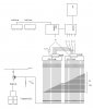
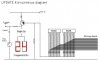
I repair pinball machines and video games. I have a test fixture i have built for testing the pinball circuit boards. I have 28 TIP102 transistors that are used for turning on and off coils on the machine. All 28 transistors are labeled say Q1 - Q28. I want to make a small two digit LED readout that would light up the number of a transistor when it is activated or even shorted. The transistor itself when turned on completes the path to ground for the coil. Im my case i will not have the coils hooked up. I just want the outputted ground signal to light the LED to the associated transistor.

Example Q23 is shorted, or activated by the built in test software.

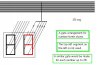
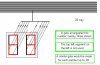
I want the LED display to read Q23.

I know the "Q" will be a given and i can fix 14 segment LED readout for the letter "Q"

What i need is a way to light the proper number from a single ground.

Any Ideas? Or any Related WEB pages?
 
Hi dragster73,

Interesting, but what if two are down ?
How would a display react ?

You might do better to have a simple
row of LEDs, one for each location,
that way if two (or more) have a problem
then the LEDs would light accordingly.

If you see two or more LEDs glow on your
row of LEDs it is, easy to see that those
ones have a problem.

How could a two digit number handle this?
Maybe alternately flashing the numbers?

A row of LEDs and resistors might be a lot
quicker and easier to construct.

Best of luck with it,
John
 
Hi John, I guess i don't like to take the easy way out when it comes to making these sort of things. I realize that the LED way would be the easy way to go but i figured if there was a small circuit design i could come up with to make this i would give it a shot.

I also had considered what to do if two transistors had a short at the same time. I figure the circuit would probably have to be software driven to accomplish this.

The only other way i would guess is to have a set of LED readouts for each transistor. This would obviously means 28 sets. This would be a easy circuit if i had the 7 segment LED readouts however even at a dollar each they would start to add up. This may even be more work then it's worth.

The other idea i had was to use a single light bulb for each transistor and just have them backlight what would appear to be a numeric readout. This would be the only other alternative to the Single LED for each transistor as you suggested.


john1 said:
Hi dragster73,

Interesting, but what if two are down ?
How would a display react ?

You might do better to have a simple
row of LEDs, one for each location,
that way if two (or more) have a problem
then the LEDs would light accordingly.

If you see two or more LEDs glow on your
row of LEDs it is, easy to see that those
ones have a problem.

How could a two digit number handle this?
Maybe alternately flashing the numbers?

A row of LEDs and resistors might be a lot
quicker and easier to construct.

Best of luck with it,
John
 
if you plan to use a led display with numbers, directly showing the noumber of the transistor, then you need a encored to encode 28 or how many transistor you have, form 20 lines, to 8 lines(bits) 4 for each digit of the display.
now, most of the encoders are priority encoders, that means that if you have lets, say Q3 and Q7 ond you will read the number with the hightest priority(the most segnifiant bit) and you will red on the display 07.
so the simeplest way is to use a led display, a row. this way you can fint out if more than one of the transistors are working at the same time and fint out the problem.
you can use square leds and have something printed with white one black like nombers, so you can directly see wich number is lit by the led behind it. 28 leds and 28 resistors would be much easier than having encoders and decoders.
also, when you use leds, you should think that they will draw some current and be careful not to overload the transistor that you connect the led to.
 
I think, the best solution a small bulbs for each transistors, with same current as coils.(good way for fault finding e.g. two out active, when only one drived.) Additionally You can make a transcoder matrix with 28 inputs and 13 outputs (two digit) it contains 202 pcs. diodes.Other way a PIC with small program.
 
but what if there are different type of coils with different type of current
one way is to connect the leds and the coils together, maybe use a buffer so that the current drawn from the transistor will not be too high.
 
The way the coils work when the boards are in the machine is this. All the coils on your pinball playfield have POWER (70 volts) Going to them all the time. The transistor (TIP 102) when activated delivers the ground to complete the circuit turning the coil on. The length of the coil being on depends on how the software in the CPU was programmed.

For what i am doing i will not be using the 70 volt coils at all. I will just be using the GROUND to turn on whatever device i decide to use to indicate what transistor is on or shorted on. EXAMPLE: If i decide to go with a individual LED and just number them i would supply 5 volts dc through the proper size resistor to one side of all 28 diodes then the other side of each diode will plug into the driver board with a molex plug connecting each of the 28 diodes to a transistor that will need to be tested. When the CPU turns on the transistor through the software it will allow the output of the transistor to connect to ground and provide the final path for the electricity to light that particular LED associated with that transistor.

Now to get fancy this is where if i knew how or had a small design on how to use decoders to do this i would love to give it a try.
 
Hi dragster73,

Yes,
i think i follow what you have in mind,
For some reason you are keen to have a number displayed.

I am kind of thinking along the lines of two 4514B ttl
chips, they also make them in cmos, but for home
constructor use, i think the sturdier ttl variety is
preferable to the easily damaged cmos type.
They also do it in a package with flying leads, but for
this i think the standard Dual-Inline-Package with 24
legs would be fine.

They are a De-Multiplexer chip, with 16 individual out
pins, and 4 bit binary input.
Using two of them should give 32 individual output
points.

The binary input section carries a latch.

I am assuming you are conversant with putting
together assemblies using chips.

See here for a pic of the 4514B chip
**broken link removed**

**broken link removed**

**broken link removed**

The suggestion is to run a free running oscilator fairly
slowly say about 6 c.p.s. and feed a binary 5bit counter
with it to get a 5 bit output A, B, C, D, E, to run
through the 5 binary outputs at about every 5 secs
roughly.

The 5 bit binary output would be used to drive the two
demultiplexers, using the 5th bit to switch between
the two, to give a 32 way rolling output signal,

Also this 5 bit binary count would go to a counter
section made to drive two 7-segment displays.

This arrangement would refer each of the 32 outputs to
the same count on the 7-segment display pair, which
would not be showing, it would be 'Dimmed'

In the event of an output encountering an earth fault,
the 7-segment display would 'Bright-Up' for about a
quarter of a second. If thats the only earth fault,
the same number would bright-up every 5 secs or so.

If two or more earth faults are present, then the
display would show each, as it occurred.

I'm trying to see an easy way to make the display stay
until the next signal, which may be the same number,
if its a different number, i'm wondering if it could
be made to change and display the next number.

This would get a bit silly if there were too many
numbers, but i think a repeating display of a few numbers
might not be confusing, if its not to fast so they are
each legible, i guess it would be unlikely to be more
than two anyway.

Just figuring out which way round the diodes would go
has worn me out! ive shown the 28 way as a 32 way, that
doesnt matter, the extra ones wouldnt show as earth
leakage.

In the diagram presented here,
i have assumed 32 wires going out to the unit to test,
each being a possible earth fault.

They are each in turn presented with an output from
a 4514B chip, with no interval in between each.

Where each outgoing wire has no earth fault,
then the base of the associated transistor will see
a high level, typically 90% of supply voltage, in this
case 5 to 6 volts, being supplied by the outputs of
the two 4514B chips.

The outputs giving a 'High' each in turn, with almost
no discernable gap between each taking its turn.

If however, one of the outgoing wires has an earth
leakage problem, then when that particular wire has
the voltage presented to it via the resistor from
the output of the decoder(4514B) it will show up.

It will show up because it would not go 'High' like
the others, and the transistor would operate.
The diode in the emitter may not be needed,
its only in case the 'High' is not high enough to
shut the transistor, but it usually is.

When the transistor operates, it puts a supply to the
7-segment displays, or maybe the Ch.En on their drivers
i havent got that far yet .....

If you think this approach is worth considering,
i will try to finalise the set-up.

It will involve a bunch of chips, and a bunch of
diodes, and a bunch of resistors.

The diagram is far from finished,
and someone else may well come up with a suggestion
that is more to your liking.

It mainly shows the arrangement for discerning an
'earthy' wire, which is the main difficulty,
as i see it.

Best of luck with your project,
John
 

Attachments

  • 28way_136.jpg
    28way_136.jpg
    54.1 KB · Views: 1,644
you know, john , i think you device will work, but what if a coul turns on for a small interval of time? and the counter passes by it, and misses?
if you increase the frequency it be very hard to see the number. and if you doint make a circuit that makes the number stay untill the next is found it will just falsh sthot maybe not even seen.
and i think that the circuit is too complicate and it doesnt give you that much info as the leds would do.
also if he has +5V and instead of connecting each led with its own resistor, you can makea 2.5 v suply, with a transistor and a zenner diode, or maybe just put 4 normal diodes in series from the 5 volts suply and you get about 2.6 volts.
also, corect me if i am wrong, but dont the transistors from the coils are keeped partialy on, so that a small current goes trough the coil?
 
Hi bogdanfirst,

Its not so easy to grasp exactly what the situation is.
But i think i have it.

In its simplest form, he has 28 connections, any of
which could have an earth fault.

He would like a number readout to indicate which has
the earth fault.

It is possible that any given board could have more
than one earth fault.

The board will not be powered up at the time of test.

The coils will not be 'hooked up' at the time of test.

Dragster73 mentions using a 'MOLEX' plug, well they
make many plugs of many types.
He says he would plug into the 'Driver Board' so i
assume it would be a multi-way connector.

However it isnt clear if this plug is something that
he might decide to fit on the board,
or if it is already fitted and he would use it to
connect for the test.

I assume its already fitted, and his intention is to
unplug the board, and plug it on to his proposed test
rig, which hopefully will read out the numbers of any
points that have an earth leakage problem.

Yes you are right, of course it would be better for
the number to stay lit, or if there are two,
then each to stay lit in turn.

And ive been trying to see an easy way to do that.

I still feel that 28 LEDs numbered 1 to 28 would be
the easiest way.
But he wants to display the number with two seven
segment devices.

I'm now wondering if any 7-seg drivers include
latches, that might be a possibility.

I'll have to read up a bit on them.

And yes, i think that the circuit is over complicated
for the job it is supposed to do,
maybe there is an easier way?

Dont forget, the fault to earth is unlikely to be
consistent, that is one may be a dead short, where
another may be just a bad leak,

So any design would have to work with that.

The more i think about it,
the more confused i get.

John
 
However it isn't clear if this plug is something that
he might decide to fit on the board,
or if it is already fitted and he would use it to
connect for the test.

I assume its already fitted, and his intention is to
unplug the board, and plug it on to his proposed test
rig, which hopefully will read out the numbers of any
points that have an earth leakage problem

Hi All..... Don't worry about the molex plug thing. I can adapt this circuit to the test fixture in may ways.

As far as the leakage thing goes as a rule the transistor on these driver boards either work ot they don't. I very rarely have a leakage problem.

I am liking all the ideas i have read so far. I am also thinking that there may be a easier way.

Check this out. www.aaroncake.net/circuits/counter.html

Would there be a way to use a counter somewhat like this and only latch on the number related to the the transistor on the solenoid driver?

Another words the counter continues to count up and down but it would only light the number that is pulled to ground. It is a rare occurance to have two transistor shorted at a time. It does happen but not to often. I figure with it scanning up and down and only lighting the numbers of a activated or shorted transistor then i would be able to display both sets of transistor or even more. They would simply count up or down and when it gets to a turned on transistor or shorted on that number would light.

One of the circuits i looked at i could adjust how fast the device would count up and down by changing a resistor to change the speed.
 
Hmmm ....

"Another words the counter continues to count up and
down but it would only light the number that is
pulled to ground."


How about if the counter tries each leg in turn,
one after the other,
and lights up the diplay on the legs that
'is pulled to ground'

And tries them all again and again,
so flashing the number with the fault ???

How about that then ??
 
Hi there,

Been having a little think.

If the OSC is fed to the counter via a 2.5k resistor,
then applying a 'High' to the counter end should not
bother the OSC, but that would stop the count from
reaching the counter.

That should hold the count at its last count.

Which would display the number it stopped at.

I think a press button could be included,
to progress the counter.

All that a press button need do,
would be provide a single negative pulse
to the counter,
which would move the count on by one,
and remove the 'High' from the earthy leg,
it would then clock round till it met another
earth fault, which may be the same one,
with the same number.

Such an arrangement could cope with many faulty
legs, displaying the appropriate number each
time, till the button gets pressed,
to move it on.

Another little diagram is included,
just to show where the 'high' could be taken.

This is only put forward as a possibility,
it hasn't been tried at all, well far as i know.

The idea of including a button to move-on
the count appears to be one way of getting
the numbers to display, without flashing.

I'm still waiting to see if a less complicated
arrangement gets put forward.

I suppose a short timer could replace the button,
but thats even more complexity, for very little
difference.

John
 

Attachments

  • CounterUpdate.jpg
    CounterUpdate.jpg
    25.3 KB · Views: 1,585
I have no problem with the button and i am really not trying to be picky but the only small problem i do see is if there are no shorted transistors and i put the tester into solenoid test it will automatically count through all 28 transistors in a matter of a several seconds. I would maybe say one transistor every second. The hole test from start to finish would take maybe 30 seconds. The test is on a loop so it then starts over. With the button it would make this very hard to operate.

After thinking about this some more i do have to agree that the single diode or even lamp for each transistor is the easy way to go. If fact the first test fixture i built for someone i used to work for just had a single lamp for each transistor.

I keep going back and forth on this project.

Take a look at this. **broken link removed**
 
Hi Dragster,

Ive just been reading through your last post.
You say you made one before,
and it had a single lamp for each transistor.
(which i have been calling potential earth faults)

I have devised a different approach which i would
like you to consider.

It is based on the info you have provided, that
such faults are usually a very definate short,
and that more than one is rare.

I suggest just a simple home made gate for each.

Thats it.

Very simple.

No chips, just a few diodes for each,
and of course the 14-segment display.
(which i assume is a double 7-segment unit)

Instant readout.

Drawback:
More than one ground will mess it up.

But it is so simple its probably worth doing.

I hope this meets with your approval,
it has cost me much aggravation
and sleep.

Regards, John
 

Attachments

  • HomeMadeGates.jpg
    HomeMadeGates.jpg
    33.4 KB · Views: 1,603
Hi Dragster,

heres another diagram of a gate.
Ive left out the supply and limiters,
i sure thats no problem.

Regards, John
 

Attachments

  • HomeMadeGates23.jpg
    HomeMadeGates23.jpg
    30.8 KB · Views: 779
Hi John, I hope you are not losing too much sleep over this.

I really like this last design. It's simple and would be relatively inexpensive.

As far as the problem with two transistors being tied to earth ground at the same time i envision this. Now bare with me here. Im not sure what type of TTL chip if any would fill this function but my idea here would be with a small relay. First off you would need 28 relays and i think they will need to have two sets of make and break contacts. One set to turn on and off the related LED and the other wired in series with all the relays to cary the power to them. What would happen is each relay would be activated when the transistor that it is attached to is tied to ground. Along with this relay turning on and providing the ground to the digit it will represent on the numeric display it will also be wired in series with all the relays. If say Q12 turns on it's relay, it will provide the completed path to light the number "12" on the numeric display. At the same time the second set of contacts in the relay have opened and thus are not allowing any other relays past number 12 to turn on. Even if there were 3 or 4 more shorted transistors down the line. The test would stop with the first shorted transistor and would go no further until that transistor has been repaired. Once all of the transistors have been repaired then the software in the CPU would allow all the digits to be lit in numeric order through the test. It would simply start with the first relay and go in consecutive order. Being nothing is shorted all 28 relays should be able to turn on and off when called upon and thus light the number 1 - 28 on the numeric readout.

My big question is this. Would there be a way to implement this using TTL and not using 28 relays.
 
Well, OOPS !!

Before someone else points it out,
I have got the diodes backwards in my last two posts.

I got carried away trying to draw them neat,
and forgot the direction!

and i cant find the EDIT
it seems to have gone ...

John
 
Hi Dragster,

yes it could.
in fact i think thats what i meant on a previous post.

The one with the button.

Where you describe it as not going further until the
repair is done,

i described it as stopping at a fault,
and displaying the number,
then if the button were pressed,
it would carry on,
til it met the next fault,
which may be the same one,
cos it just goes round and round.

Maybe i didnt describe my intention properly
but what you said using relays,

is just what i meant using a button.

John
 
The problem i see with the button is this. In self test i would have to push the button every time the CPU activated one of the transistors. This would mean after Q1 was activated your devise would stop but the test fixture will have already moved on two Q2 before i have even had the chance to push the button.

Once all of the transistors are good i can have the test fixture turn on each transistor in consecutive order for 1 - 28 and then back to one just like the counter design we were talking about.

Using a relay type circuit they will not need to be reset.
 
Status
Not open for further replies.

Latest threads

New Articles From Microcontroller Tips

Back
Top