Continue to Site

Welcome to our site!

Electro Tech is an online community (with over 170,000 members) who enjoy talking about and building electronic circuits, projects and gadgets. To participate you need to register. Registration is free. Click here to register now.

  • Welcome to our site! Electro Tech is an online community (with over 170,000 members) who enjoy talking about and building electronic circuits, projects and gadgets. To participate you need to register. Registration is free. Click here to register now.

LED Music Sync Project

Status
Not open for further replies.

kyled921

New Member
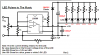
I want to build a Ipod charger that plays music and is syncronized to music. I found a previous thread by audioguru and am currently working on a circuit prototype. I Want several LEDs of different colors (Red, White, and blue/green) all synced in same circuit. I also want to be able to send the audio from the ipod to an external audio jack and a speaker for the charger.
Here is the previosu thread:
https://www.electro-tech-online.com/threads/leds-sync-to-music.21890/
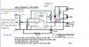
Here is the basic idea for my circuit...
DC wall adapter------Charger----iPod/MP3----Speaker, and Audio port out----both speaker and audio out syncronized to LEDs
 
Okay, here is my updated flowchart 2.0 so my idea can better be represented.:)
 

Attachments

  • untitled.JPG
    untitled.JPG
    18.8 KB · Views: 1,054
Your flowchart is missing an Audio Spectrum Analyser which is a very complicated circuit.
It has about 20 frequency bands each with a filter, a rectifier and peak detector. It has about 20 bar graph driver ICs.

New circuits do it with a microprocessor that needs to be programmed.
 
The equalizer is just for emphasis, its not actually part of the circuit. I was using to show that the LEDs are in sync with the msuic.:) Sorry for the confusion, I just want the LED sync circuit, no equalizer.
 
An equalizer has adjustable filters that change the sounds of the music. It has many adjustments.
An audio spectrum analyser has filters and LED bar graphs to show what the sounds are doing without any adjustments possible.

Some equalizers have a spectrum analyser.

A LED sync circuit has no filters and has one bar graph or one LED to show the beat of the music. It does not show different frequencies like a spectrum analyser does.

Hi
Can you point out a good tutorial on Spectrum analysers? I fancy trying this out.

Building filters , adding channels right to the basics anything that would help me understand whats required.

Cheers
 
Here is an Audio spectrum Analyser project. I think its LEDs will be dim because the LEDs and drivers are multiplexed.
Parts of the text are in Vietnamese:
 

Attachments

  • Audio_Spectrum_Analyzer.pdf
    457.1 KB · Views: 857
All I want for my circuit is for the 6 LEDS (2Red, 2white, 2 blue) to all pulse at the same time to a bass or low mid-range frequency. No fancy equalizer stuff, just all 6 flash at once with music beats.
 
Alright, I am constructing your circuit shown here from a previos thread and I have a few questions. I put them on the drawing for easy reference. I fogot one...Where do you plug in the audio cable so music comes into the circuit?
 

Attachments

  • untitled 2.JPG
    untitled 2.JPG
    52.2 KB · Views: 1,167
Can you link the original version and thread of that diagram? It would be easier to explain it to you if I could see the original.

Since all you want is something to flash with the beats in the music, here is what I would do:

use a unity gain buffer to take the audio from your ipod plug. make sure the buffer is good enough to use for audio (i.e. slew rate, THD @ unity gain, etc).

From the output of your buffer, you will go to the speakers as usual. You will also go to the input of a simple low pass filter (RC) with a corner frequency somewhere in the midrange (say, 500Hz or 1kHz).

The output of this filter can go to one input of a comparator. The other input of the comparator should be tweaked so that only certain volume levels will set it off.


I'm not sure if thats the simplest way to do it, its just what occurred to me off the top of my head.
 
My circuit is shown made on stripboard. Stripboard is perforated and has horrizontal strips of copper that connect some of the parts together. The blue line are the copper strips. The red X's are where the strips must be cut (with a drill bit) so that the wrong parts do not connect together.

For example, pin 1 of the LM386 must not connect to anything, the same with pin 7 and pin 8.

You circled a 1N4148 diode that is not an LED. It should be a 1N4001 diode when you drive 6 LEDs.
The Vin is the audio input. You correctly found the input ground. the +9V and 0V are the 9VDC battery or power supply.
The 10k pot is a level adjustment trimmer.

My sketch shows only one LED and the current-limiting resistor for it. Add the other 5 LEDs and current-limiting resistors to the same connections.
 
Can I connect all 6 LEDs in a series with a single resistor totalling the sum of the LED R's (I calculated 1040 Ohms, but Im only using 1K with a 5% variation, so 950 to 1050 Ohms)?
 
Can I connect all 6 LEDs in a series with a single resistor totalling the sum of the LED R's (I calculated 1040 Ohms, but Im only using 1K with a 5% variation, so 950 to 1050 Ohms)?
Red LEDs are about 1.8V each.
White LEDs are about 3.5V each.
Blue LEDs are also about 3.5V each.
If they are in series then their total voltage is 17.6V plus about 25V for the 1k current-limiting resistor so the drive signal needs to be +42.6V which is much too high for the LM386 amplifier IC.
 
So will I have to build a seperate circuit for all 6 LEDs? Im trying to fit this project inside a model car 1/24th scale, so about 10"x4" and 1" tall. Is it ossible to put maybe 2 reds on one circuit, 2 blues on another, and 2 whites on a third? Or could I mix and match? (Basically, what would be the most voltage I could put on the LM386?)
 
Oh, and what is the ground for the audio cable. I was going to cut a standard 2 chord headphone/audio cable with L and R channels, is a certain one the ground and the other the Vin?
 
Two 3.5V LEDs in series need 7V plus 2V for a current-limiting resistor plus 2V for the LM386 headroom and diode. Then the total supply must be at least 11V. The datasheet for the LM386 shows its max allowed supply is 12V for some of them.
You will not find a 12V battery that does not drop below 11V that has enough current in the tiny size you want.

Connect the LEDs each with its own current-limiting resistor. Then the highest voltage LED is 3.5V plus 1V for the current-limiting resistor plus 2V for the LM386 headroom and diode. Then the minimum battery needed is 6.5V and a 9V battery will work for a while.

Headphones have a left signal wire, a right signal wire and a ground wire. Feed the two channels through two series 1k resistors that join at the volume control for the LM386. Connect the grounds together.
 
Okay. So do you mean Each LED has a resitor, and the LEd-resistor combos are connected to the LM386 all in series or parallell? Or will I have to build a seperate circuit for each LED and resistor, totallig 6 of these LM386 sync circuits?


You will not find a 12V battery that does not drop below 11V that has enough current in the tiny size you want.
I can use a 12V adapter. I'm currently going to use a 12V breadboard to test the original circuit.
Also, how would I make it so the LED flashes at a low frequency (40-150-HZ roughtly)
 
Make it like this and use a 9V adapter:
 

Attachments

  • LED pulses again.PNG
    LED pulses again.PNG
    31.4 KB · Views: 914
Thanks soooooo much. I will test it out once I get some of the materials neded from Radioshack. Audioguru is AWESOME!!!
 
Status
Not open for further replies.

Latest threads

New Articles From Microcontroller Tips

Back
Top