Continue to Site

Welcome to our site!

Electro Tech is an online community (with over 170,000 members) who enjoy talking about and building electronic circuits, projects and gadgets. To participate you need to register. Registration is free. Click here to register now.

  • Welcome to our site! Electro Tech is an online community (with over 170,000 members) who enjoy talking about and building electronic circuits, projects and gadgets. To participate you need to register. Registration is free. Click here to register now.

LED Matrix Help

Status
Not open for further replies.
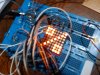
I have finally had the time to test my design properly on breadboard, everything seems to be ok :)

(And yes I can make messy breadboards :D )

It's just using some little pnp transistors I had lying around, will see about ordering those mosfets tomorrow.

Even though there is only 1 display hooked up, it is running the code to run 10 of them, and no flicker which is good, and what I was worried about, hence being patient before carrying on.

I can now see about animating the static image and working on the display routines etc.

Thanks for the help so far :)
 

Attachments

  • 2009-06-19 22.11.46.jpg
    2009-06-19 22.11.46.jpg
    66.7 KB · Views: 173
Further Progress

It's been a while but I have finally managed to find the time to make some progress on this.. and now have a couple of questions :)

Attached are a couple of diagrams, one the simple row driver using p-type mosfets, the other the column drivers, one for the green leds, one for the red leds, using 595 shift registers... the green column has the darlington array drawn in.

The question being, do I actually need the darlington array on the column driver, as I understand it, the current is being supplied(sourced?) by the row driver fets, and the shift registers just provide a route to ground, and do not pass the current?

TIA :)
 

Attachments

  • 10xDisplay 001.jpg
    10xDisplay 001.jpg
    74.4 KB · Views: 213
  • 10xdisplay 002.jpg
    10xdisplay 002.jpg
    91.2 KB · Views: 189
The max allowed output current from a 74HCxxxx IC is 25mA which will look dim like 25/16= 1.6mA continuously since your display is multiplexed and each LED is turned off for most of the time. You need to blast a high current into the LEDs for them to look bright.

The current in the Mosfets, LEDs and column drivers is exactly the same since they are in series.
 
Sorry I don't understand why 25ma/16?

I thought I had it in my head that the shift register could do 25ma per output, not in total :) maybe I was thinking of the darlington array..

But regardless I need to keep the darlington array in then and ofc add it to the other column, thanks, I knew there must have been a reason why it was in my original design, but that was so long ago I forget :)
 
Sorry I don't understand why 25ma/16?
The max allowed output of a 74HCxxxx is 25mA. Since you have 16 columns and only one column is lighted at a time then a column is turned off for 15/16 of the total time and will appear dim like an LED with a continuous current of only 25/16= 1.56mA.

You need to blast a high current to the LEDs with some ULN2803's and the Mosfets so that the LEDs will appear bright enough.
 
The 8x8 matrix is bi colour, and has separate red and green. The columns are split into 8 each of red and green. Each colour will have it's own shift register, so 2x 595 per matrix, and will ofc need 2x 2803's.

So to me it would make sense if you meant 25/8, but still I need the 2803's for the reason you mentioned, so all irrelevant I guess.
 
Status
Not open for further replies.

Latest threads

New Articles From Microcontroller Tips

Back
Top