Continue to Site

Welcome to our site!

Electro Tech is an online community (with over 170,000 members) who enjoy talking about and building electronic circuits, projects and gadgets. To participate you need to register. Registration is free. Click here to register now.

  • Welcome to our site! Electro Tech is an online community (with over 170,000 members) who enjoy talking about and building electronic circuits, projects and gadgets. To participate you need to register. Registration is free. Click here to register now.

LED/LCD circuit design

Status
Not open for further replies.

cyrusthevirus

New Member
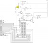
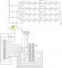
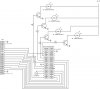
I am looking to design a circuit which will power 100 - CREE XR-E LEDs. (50 white and 50 blue) The LEDs have a forward voltage of 3.7V and an input current of 1000mA. The LCD requires an input of 5V for both the backlight and the circuit and a current of 120mA for the backlight and 1.3mA for the circuitry. The PIC24 is a PIC24F64GA002 which has a voltage requirement of 3.3V.

I have started to put together a circuit but I am running into problems. I am not sure if I should use a MOSFET or NPN between the LED and the PIC. I am also not sure how to arrange the LEDs? Parallel? Series? Both?

The purpose of the project is to develop a light which will rise in brightness to simulate a sunrise and then dim at night to create a sunset. Then at night the blue would be used to simulate the sunset.

I plan the use PWM to control the duty cycle of the LEDs.

The LCD would be used to display the current time of day.

I have not writted the program yet because I wanted to make sure I had the circuit correct so I did not fry out the LEDs, LCD or the PIC.

Thanks for your help.

I have attached a starting circuit for conversation.
 

Attachments

  • PIC24.jpg
    PIC24.jpg
    51.1 KB · Views: 2,546
The LEDs need current limit resistors (even if they are PWM).

The LEDs are backwards.

The LEDs should be in series strings because they do not share current well in parallel.

3.7V 1000mA is a lot of power (3.7W) for each LED, they will require very big heat sinks.

I would use logic driven MOSFETS for the transistors.

10K is too large for a gate (or base) resistor. Recheck your math.

I did not look at the LCD interface.
 
Change your 10k resistors for 330 ohms, to drive the transistors better. Your LEDs are reversed, so fix that, and you need resistors in series with each LED string to control the LED current when the LEDs are on. The resistor value depends on the LED forward voltage and your PSU voltage (currently shown as ?). :)

For the LCD you only need 4 wires to the DB4-7 pins (not 8 to DB0-7). Most LCD code you will get is 4bit code bacuase it uses less pins. You can also tie the R/W pin of the LCD to ground as you dont need to read the LCD to use it as a display, and you need a 10k trimpot 0v-5v with its wiper attacked to Vo to control the LCD contrast.

Finally you need a series resistor for the LCD backlight, most will draw too much current if you connect direct to 5v. About 220 ohms is typical, maybe use a lower value if the backlight is too dim.

(edit) Whoops someone beat me too it! ;)
 
Last edited:
Okay, I have adjusted the LEDs and added the resistors (except for the Thanks for all of your help. This is my first attempt at developing a circuit. contrast on the LCD). I added the mosfet, but I was not sure where of the connects go to. Can you suggest a model number for the mosfet?

Because this was my first program to control the LCD, I was planning on using the full 8 channels instead of four. Is that a bad idea? I was also planning on using PMP to communicate with the LCD. Can I do that over 4 channels instead of 8?

If I use the LEDs in series then my power supply will need to be 25 * 3.7 = 92.5 V in size. Is there a better way so I do not need such a large power supply while still being able to control the LEDs via PWM over 4 channels?

My prototype will have large heatsinks and fans to keep the leds cool.
 

Attachments

  • PIC24_2.jpg
    PIC24_2.jpg
    52.1 KB · Views: 943
Hi again. Hmm a hundred 3 watt LEDs?? That is a pretty serious amount of light. Have you considered just using 4 100w lightbulbs and some triacs to drive them?
 
As to the size of your power supply;
(Parallel) 3.7 volt at 100 amp
or
(series) 92 volts at 4 amps
same size supply
 
hey!! can anyone plz help me by giving me some practical examples of control engineering on which i cam give a presentation . .??? plzzzzz
 
The light is for an aquarium. 100w light bulbs do not provide the right wavelength and produce too much heat.

As for the power supply, I know that I will need about 100 watts of power for each string of 25 leds. However I would rather be able to use a 4 amp/25 volt supply instead of trying to find a 100 volt supply. Thoughts? My idea may not be based in theory and only in cost and availability of power supplies.
 
25V (24?) strings actually looks like a better idea especially for a home built project to be used near water. The LEDs would probably end up in strings of about 6 (22.2V nominal) with maybe 3.9 ohms 5W in series with each string.

Is this a really big aquarium? 370W of LED light is a lot!
 
The aquarium is 90 gallons, but there is also a component of the aquarium called a refugium. Overall I beliieve I will need about 100 bulbs, although I could get away with about 80. I am basing my design on: Reef Central Online Community - DIY LEDs - The write-up

Their design does not use an IC. I like the use of an IC to be able to set the sunrise and sunset. After I get this up and running, I plan to add a PH and temperature sensor. Then I may add an automatic feeder.

So if I run each string of 6 LEDs can I still control them through four channels?

Can I also run them from the same power supply?
 
You really wont need the LM317's. Just put a series resistor on each LED string once you get to testing stage and you know PSU voltage etc.

I would also put a cap in parallel with each LED string (after the resistor), you don't know how their little fish eyes are going to react to pulsing high power light all day long, even if it is too fast for humans to see small animals have faster nervous response in general, I would aim for a constant brightness of the LEDs if at all possible.

Now comes the tricky part... How big a PSU do you need? I guess you don't need to drive all the LEDs at once?
 
I would be driving all of the LEDs at once. The only time I would not be driving them all would be at night and during sunrise/sunset.

I am proposing to use 4 - 24V 3A supplies and then a seperate power supply to run the LCD and PIC.

What model number capacitor do you recommend?

If I do not include the LM317 and one of the LED's blows, won't I be sending the extra current through the remaining strings?
 
Status
Not open for further replies.

Latest threads

New Articles From Microcontroller Tips

Back
Top