Hi everyone,
I successfully completed my 8x8x8 LED cube (by CHR) (https://www.instructables.com/Led-Cube-8x8x8/) some months ago. The vague idea is that an ATMEGA32 sends data to shift registers which then store it and choose which LEDs to give the most percentage on time in the PWM signal sent to the column (apologies for absolutely botching this).
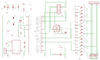
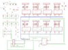
Recently decided I wanted to make it more portable by simply adding a 3xAA battery pack to power it. However, in the process of completing that (taking the boards out of the casing and adding in the battery pack to the power lines), my cube has now started running into issues. The issues may have occurred before this changeover but not that I was aware of. I have attached schematics of the boards below.
In particular, the cube appears to struggle to draw patterns upwards or downwards when lighting up more than a few columns. Roughly 90% of the animations from CHR (original instructable poster) and SuperTech-IT (a second 8x8x8 LED cube instructable poster https://www.instructables.com/CHRs-8X8X8-LED-Cube-Revisited-with-improvements/) work flawlessly.
The first video shows a diagnostic test. It shows that each column can be lit up without issue. The diagnostic is then meant to light up each and every LED one by one from the bottom. However, mine instead appears to light up each layer (via each LED) one by one, but the last verticle plane always fails to do so. In the end the whole cube is meant to be lit.
In the second video, it shows more clearly the issue my cube has with lighting up each of the horizontal layers one by one. This is shown when it looks like a single column lights up dimly. It also shows how other (potentially less power consuming) animations work flawlessly.
These tests make me vaguely think it could be something to do with the transistor layer select array however I am not sure (the instructable used PN2222 transistors as it was what they had laying around, I followed this as I too had them lying around). Any advice would be beyond appreciated.
Thanks
I successfully completed my 8x8x8 LED cube (by CHR) (https://www.instructables.com/Led-Cube-8x8x8/) some months ago. The vague idea is that an ATMEGA32 sends data to shift registers which then store it and choose which LEDs to give the most percentage on time in the PWM signal sent to the column (apologies for absolutely botching this).
Recently decided I wanted to make it more portable by simply adding a 3xAA battery pack to power it. However, in the process of completing that (taking the boards out of the casing and adding in the battery pack to the power lines), my cube has now started running into issues. The issues may have occurred before this changeover but not that I was aware of. I have attached schematics of the boards below.
In particular, the cube appears to struggle to draw patterns upwards or downwards when lighting up more than a few columns. Roughly 90% of the animations from CHR (original instructable poster) and SuperTech-IT (a second 8x8x8 LED cube instructable poster https://www.instructables.com/CHRs-8X8X8-LED-Cube-Revisited-with-improvements/) work flawlessly.
These tests make me vaguely think it could be something to do with the transistor layer select array however I am not sure (the instructable used PN2222 transistors as it was what they had laying around, I followed this as I too had them lying around). Any advice would be beyond appreciated.
Thanks
Attachments
Last edited:
