Torben
Well-Known Member
ljcox said:Here is an electronic option that occured to me last night.
Neat. That's what I almost arrived at last night but I didn't quite make it. Thanks for the explanation!
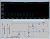
When I simmed this in LTSpice, it occurred to me that the resistor values are fairly important if you don't want the brakes dimming the turn signals or vise versa. For me (in the sim) 47k for R3 and 56k for R4 worked OK.
It put me in mind of the various devices I've seen which dim some indicators when others turn on.
Also the sim didn't require an incandescent bulb for the flasher--I'll have to try this in real life, but in the interim, is this something which could be explained by sim/real world differences?
Thanks again,
Torben
")
") ]
]