Torben
Well-Known Member
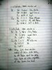
ljcox said:I still can't make any sense of it. So I've drawn the attachement.
Please measure the voltages (without the 100 k resistor) at the C, B & E of both transistors for each case.
A point that just occurred to me is the that EB junctions will go into Zener breakdown if the supply is 12 Volt. And it may occur at 6 Volt.
I did my measurements and got what's in my attachment.
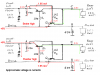
From the fact that I need 2K2 base resistors instead of 2.2K, which I also get from basic calculations, I think my Radio Shack "similar to 3906" transistors are not that similar to 3906s after all. The 2k2s work in the sim but not on the breadboard.
As an aside, I tried simplifying and going back to my books, and found that in the sim, the 100k resistor to ground was not needed if I put 22K pulldowns on the bases of both transistors. I don't think the pulldown is needed on the base of the PNP which has its emitter to the brake line.
This bombed on the breadboard. But the version with 2K2 base resistors and the 100k resistor to ground from the left flasher input line works great.
I'm stumped for tonight. I'll have another look tomorrow.
Torben
[Edit: Oops. Uploaded smaller image. Also, I just tried this with 2K2 base resistors, a 220K pulldown on the base of Q2 (the transistor bridging the brake and flasher lines; I call the one interrupting the flasher line Q1), and no 100k resistor--and voila: it works fine. i.e. it follows the truth table you posted.]
Attachments
Last edited:
")
