Continue to Site

Welcome to our site!

Electro Tech is an online community (with over 170,000 members) who enjoy talking about and building electronic circuits, projects and gadgets. To participate you need to register. Registration is free. Click here to register now.

  • Welcome to our site! Electro Tech is an online community (with over 170,000 members) who enjoy talking about and building electronic circuits, projects and gadgets. To participate you need to register. Registration is free. Click here to register now.

LED array schematic help

Status
Not open for further replies.

SmurfTacular

New Member
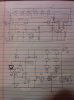
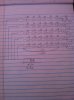
Im pursuing a homemade photography LED array. Ideally, the LED array will be 6 series 5 parallel. (24 volts @ 1000mA per row). Each LED row is a different wavelength, together they make up the whole spectrum. Each LED row I want to have adjustable so you can adjust the color temperature and enhance the photo. They do already exist but there not very powerful, besides I wanna make one for fun. But I ran into a problem with figuring out how to dim them. Potentiometers in series with each array will burn up to much electricity. I'm still learning how to draw schematics. Will this work at all?
 

Attachments

  • IMG_0891.JPG
    IMG_0891.JPG
    2.1 MB · Views: 291
From your schematic it looks like you have AC going to your LEDs. You need DC. You might want to share your LED types as different LEDs have different voltage drops, so to make sure we need to know this. If they are really 1 amp LEDs the pot is probably not the best option because of the power.
 
I figured I would need some sort of voltage or current regulator... I'm proficient in soldering, is there a schematic I can follow and make my own? All the LED's fV is 3.6 @ 1A. (ive stressed them to 4v with no problem if heatsinked).
 
Maybe you do not understand.
First you need a rectifier circuit to convert AC to DC.
Then you need a complicated PWM circuit to dim each colour string of LEDs.
Maybe somebody here will design a circuit for you (for free?).
 
Do you already have a transformer? If so what are it's specs.?

Yes a current regulator might be best. Lets see.
 
1. Yes, you could do what you have sketched, replacing the rheostats with adjustable voltage regulators (LM317-type thingies). However, as was pointed out in the other thread referenced above, you're going to end up wasting a lot of power as heat. So ...

2. The mo' betta' way to do this would be to use PWM. Don't worry, doesn't have to be all that scary and complicated. I've built simple PWM controllers using a single 555 and a transistor (plus a few resistors, etc.). Very little power wasted, and better control over brightness, especially at the lower end of the scale.

3. I like the idea of mixing different colors of LEDs to see what the result is. You're going to interleave them together (physically), right? so that the colors mix better? Be interesting to see how this works. LED light by itself is pretty horrible, certainly not anywhere near ready for most household lighting tasks.
 
Maybe you do not understand.
First you need a rectifier circuit to convert AC to DC.
Then you need a complicated PWM circuit to dim each colour string of LEDs.
Maybe somebody here will design a circuit for you (for free?).

Ohhh OK. Yeah I would like to do that but I dont know how to figure that out yet haha. But I can follow a schematic if somebody would be generous enough to produce me one :)

Do you already have a transformer? If so what are it's specs.?

Yes a current regulator might be best. Lets see.

No thats just a theoretical transformer I jotted down. 12v 6A is ideal.


LED light by itself is pretty horrible, certainly not anywhere near ready for most household lighting tasks.

I'll have to stop you there. You can buy any color temperature LED you want for your home, whether that be 4300K or 6050K... Mixing precise wavelengths of light together is the most accurate way of producing any form of mixed light.

I dont know why LED's have such a bad rep for that :confused:
 
Last edited:
Here is a 555-based PWM dimmer circuit custom-made for LEDs:

**broken link removed**

Pretty simple. Can be adapted to different configurations of LEDs.
 
Wow thanks alot. That's exactly what I'm looking for. So could I substitute those LED's on the schematic for six 3.6 fV Cree LED's? And how exactly do you dim the circuit? With a potentiometer?
 
Wow thanks alot. That's exactly what I'm looking for. So could I substitute those LED's on the schematic for six 3.6 fV Cree LED's?

Wellll, you need to wire your LEDs according to your power supply voltage. If you use that PWM circuit running on 12 volts, then you could have strings of 3 3.6V LEDs in series, with the strings in parallel (with current limiting resistors, of course).

And how exactly do you dim the circuit? With a potentiometer?

Yep; that's what the thing labeled "P1" is in that circuit. Just an ordinary pot.

[Ramble: I hate that style of drawing schematics that shows resistors as rectangular blocks! Should have the zigzag lines of classical schematic symbology, as [insert name of deity here] intended.]
 
Do not use PWM if you are going to take photos.

(I'm no fan of PWM anyhow, as I can sometimes detect LEDs flashing at 5 kHz with the naked eye. The 100 Hz ones on the back of some cars are just plain stupid.)

If you have a PWM at 200 Hz, and you take a photo at 1/250th, then you will get a random 80% of the cycle. If you take a photo at 1/1000th, you will get a random 20% of the cycle, which is likely to be full on or full off. Mix that across several colours, all flashing with random phases, you can get absolutely any colour, and the photo certainly won't look like it appears in real life. Even at 1/60th of a second, you will get 3 and a bit cycles. The 3 cycles will average to what you want, but the remaining bit will be randomly somewhere between on and off, so you will get about a 10% variation on the brightness of each colour.

Go for adjustable currents. You do not get a great deal of heat dissipated, because the LED voltage does not change a lot. This is completely different from dimming incandescent lights, where the voltage changes a lot and the current changes less when they are dimmed.

If you use something like the "1A Voltage-controlled current sink" from this data sheet https://www.linear.com/ad/19-current_control.pdf that will work very well.

If you have a 12 V supply, and three 150 mA LEDs in series, they might be 3.4 V at 150 mA and 3 V at 50 mA.

At 150 mA, the voltage drop in you current control device is 12 - (3*3.4) = 1.8 V so the power it has to handle is only 0.15 * 1.8 = 0.27 W

At 50 mA, the voltage drop is 12 - (3*3) = 3 V so the power is only 0.15 W.

If you use PWM, the maximum power is the same, because that occurs at 100% duty cycle so the current is on 150 mA all the time. The power dissipation at 33% duty cycle is 33% of 0.27 W which is 0.09 W, so less power is dissipated at light loads in the current control device, and more in the LEDs.
 
Low frequency PWM for the rear lights of cars makes a pattern when you move your eyes that creates 20 cars or more for each real car.
 
Do not use PWM if you are going to take photos.

(I'm no fan of PWM anyhow, as I can sometimes detect LEDs flashing at 5 kHz with the naked eye. The 100 Hz ones on the back of some cars are just plain stupid.)

I can see how that would be a problem, but can't you just crank up the frequency so it's somewhere below the persistence of vision threshold? What's the effective upper limit of PWM frequency when using it on LEDs?
 
Whats the persistence of vision threshold for a camera?
 
Whats the persistence of vision threshold for a camera?

I was assuming the visual sensor was a human eyeball. Who cares about cameras? (Unless one of your requirements is that drivers behind you be able to take good-quality photos of your message board!)
 
Thanks for the suggestions on the LED frequency, but I'm not sure if that will matter or not. This is going to be used indoors, most likely for portraits.

I have redrew these two beautiful schematics provided from Diver300 and Carbonzit, thanks.

Witch of these two would be most ideal? (Each LED can take 4.0V @1A)
 

Attachments

  • IMG_0893.JPG
    IMG_0893.JPG
    2.2 MB · Views: 224
That wasn't the circuit that I was thinking of.

I suggested the one that does not switch on and off, but it keeps the current steady. It is at https://www.linear.com/ad/19-current_control.pdf and it is the bottom right of page 3, and it is called "1A Voltage-Controlled Current Sink".

You should not put the strings in parallel. The best idea for LEDs that can take 1A is to have the control circuit exactly as shown for each string of 3 LEDs.

Whatever circuit you use, 12 V for 3 LEDs in series might be too low. The LEDs are rated at 1A, and the maximum forward voltage at 1A is 4 V. You need 1 V drop across the 1 ohm resistor, and something across the MOSFET. However, you may well find that the LEDs only need 3.5 V so you could be OK. Otherwise, increase the supply voltage or have three strings of two LEDs.
 
carbonzit said:
Who cares about cameras?

Apparently, the poster does, considering the first line of his first post says:

SmurfTacular said:
Im pursuing a homemade photography LED array.

I hate the PWM'd LED taillights on most newer cars, too. Very annoying and distracting. I have seen some which were such high frequency that I couldn't see them strobe. Those may have been current controlled instead of PWM.
 
Status
Not open for further replies.

Latest threads

Back
Top