Continue to Site

Welcome to our site!

Electro Tech is an online community (with over 170,000 members) who enjoy talking about and building electronic circuits, projects and gadgets. To participate you need to register. Registration is free. Click here to register now.

  • Welcome to our site! Electro Tech is an online community (with over 170,000 members) who enjoy talking about and building electronic circuits, projects and gadgets. To participate you need to register. Registration is free. Click here to register now.

LCD won't display?

Status
Not open for further replies.

MrDEB

Well-Known Member
wondering if its in the code is the problem?
using a hd44780 but no display.
The backlight lights up, screen seems to flicker.
Adjusted the pot but no display
any suggestions?
Code:
Device = 18F2420
Clock = 20 // 
//Config OSC = INTIO2

// some LCD options...
#option LCD_DATA = PORTB.0              // Assign the LCD connections
#option LCD_EN = PORTC.6                //
#option LCD_RS = PORTC.5                //

// import LCD library...
//Include "InternalOscillator.bas "
Include "LCD.bas"
Include "convert.bas"
Dim Variable As Word

// Start Of Program...
DelayMS(550)                            // Let the LCD warm up
LCD.Cls                                 // Clear the LCD screen
LCD.WriteAt(1,1,"Hello World")
                                             // Send some text to the LCD
Variable = 0                            // Clear the "Variable" register
While True
   Inc(Variable)                       // Increment the "Var1" register
    // Convert to a string,
    //  and always display 5 characters   
    LCD.WriteAt(2,1,Convert.DecToStr(Variable,5))   
   
  DelayMS(1000)                       // Delay for 1 second                 
Wend
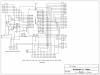
need to locate schematic if needed? basic 4 data lines connections.
Tried changing the C6 C5 to C5 C6
 
Portb is Analog You need a ADCON1 =%00001111 in there if you want to use a LCD data on portB


Mike this Inits the LCD Include "LCD.bas" but for some reason it doesn't set port pins right on all chips.

This should work
Code:
Device = 18F2420
Clock = 20 // 

 
// some LCD options...
#option LCD_DATA = PORTB.0              // Assign the LCD connections
#option LCD_EN = PORTC.6                //
#option LCD_RS = PORTC.5                //
 
// import LCD library...
Include "LCD.bas"
Include "convert.bas"
Dim Variable As Word
 
// Start Of Program...
ADCON1 = %00001111  //All digital
DelayMS(550)                            // Let the LCD warm up
LCD.Cls                                 // Clear the LCD screen
LCD.WriteAt(1,1,"Hello World")
                                             // Send some text to the LCD
Variable = 0                            // Clear the "Variable" register
While True
   Inc(Variable)                       // Increment the "Var1" register
    // Convert to a string,
    //  and always display 5 characters   
    LCD.WriteAt(2,1,Convert.DecToStr(Variable,5))   
 
  DelayMS(1000)                       // Delay for 1 second                 
Wend
 
Last edited:
Thanks Burt
I was wondering if perhaps that there was something about the port setup seeing how I tried this same code on two different Pics.
Will give it a try
THANKS again.
 
The code works I tested it on hardware so if you can't get it going you have a hardware problem
 
It should work but it dosn't.
When I get back from the fair grounds tonight going to recheck my wiring but trying out using two different pica
2420 and a 4520
also going to try a different LCD display.
Looking at the C port as well
 
There not any thing wrong with PORTC it's I/O only

You hook the LCD up like this

Portb.0 to lcd data4
Portb.1 to lcd data5
Portb.2 to lcd data6
Portb.3 to lcd data7
LCD_RS to PORTC.5
LCD_EN to PORTC.6
LCD_VO to a pot center tap top a VDD and Bottom at GND
LCD_VSS to GND
LCD_VDD to 5 volt
LCD_backlite A to 5 volts
LCD_backlite K to GND may need a 120 ohm resistor some have one on the LCD

And gnd the unused pins RW, Data0, Data1, Data2, Data3.
 
Last edited:
Here you something to go by

**broken link removed**
 
Last edited:
Only difference I have is a 330 ohm resistor on pin 15 and the unused data pins are not connected to anything.
I have had this display working along time ago.
This is frustrating. Its got to be something simple?
second look? you have B.0, B1, B3, B4
what happened to B.2--mistype??
 
Mistype sorry.
Most of the lcd that have back lights don't even need a resistor there on the LCD but i would check to make sure any way.

If the code I posted doesn't run you have a hardware problem some where. It runs find I did try it. With pic and LCD.

I have had some problems with cheap trimpots from radio shack there easy to turn past the stop and it breaks them.

I always use portb.4 and up I should of looked over that post I fixed it have re looke
 
Last edited:
I may have located problem Should the E pin change voltages. I get a constant 4.7 aprox
The RS pin shows 2.? mv
will re verify as I got dinner to get to cooking before the boss gets home!!
YEKS its 508pm
 
E gos low and high but it is fast you'll not see it with DVM I redid this it was kind of fast and I had Vdd on bottom and grd on top but it's not showing as planed
so have a look agin
**broken link removed**
 
Last edited:
Tomorrow I am going to pull the PIC out and using a DMM, check that each pin that is supposed to be connected is connected to its proper LCD point.
Been checking using DMM but testing just the plug/ribbon cable/plug/LCD pins.
Perhaps a pin on the LCD header is not correct or not soldered correctly?
Checking and REchecking hardware from point A to point D and everything in between.
 
Tested everything but still?
My next trick is --start over. Build a new LCD board then start from scratch
 
MrDeb I did this last night have a look it's a simple board you should make one something like this.
It will save you some headaches
 

Attachments

  • USB18F2520BE.png
    USB18F2520BE.png
    17.8 KB · Views: 162
Here is my simple board

Been using this board as well as the Tap-28.
Very simple but it works (I think my LCD woes are between the board and the LCD)
Using the Tap-28 I need a bunch of jumpers. Been contemplating using the Junebug to test the LCD.
This simple board has provision for testing port outputs (8 LEDs ( 4=LOW and 4=HIGH)
An LCD header
a UART switch that I have to get the bugs out of?)
I will copy schematic if I get time?
 

Attachments

  • dev board top.png
    dev board top.png
    108.6 KB · Views: 149
  • new dev board.png
    new dev board.png
    41.9 KB · Views: 161
schematic of dev board

Here is my latest design
Very easy
 

Attachments

  • dev board sch.png
    dev board sch.png
    110.4 KB · Views: 169
Status
Not open for further replies.

Latest threads

Back
Top