Continue to Site

Welcome to our site!

Electro Tech is an online community (with over 170,000 members) who enjoy talking about and building electronic circuits, projects and gadgets. To participate you need to register. Registration is free. Click here to register now.

  • Welcome to our site! Electro Tech is an online community (with over 170,000 members) who enjoy talking about and building electronic circuits, projects and gadgets. To participate you need to register. Registration is free. Click here to register now.

LCD won't display?

Status
Not open for further replies.
Junebug w/LCD/SF

Having issues w/ LCD won't display Tried two different PICs as well as two different LCds
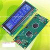
All I get are the little squares.
Checked and rechecked all wiring
Planning on hooking up a Junebug directly to the LCD but only have A.1-A.4 available and Swordfish won't allow .
Only a 0 or a 4 are allowed not a 1
Something really wrong. Am thinking maybe the Junebug is not operating correctly?
Can get an LED to blink.
going bananas in Idaho
about ready to try a third LCD
 
Maybe I wasted my time like most times I hope this helps you.The thing I think is happen here is you have a broke track on your home made board.

I would run the test as listed in he diagram posted here

Make a simple while loop to test each pin RS,E and the data pins

Some thing like
Code:
Dim led as PORTB.0 // And change for each pin I no this takes time and could be done easy but you'll sure see what is happen this way 
//Do this for each pin your testing one at a time new hex and all.reload the pic chip 

while true 
    high(led)
     Delayms (1000)
    low(led)
wend

This will show you where you hooked what pin and if there working

I make a home made board and all I got was nice squares

After hours of looking the board over I couldn't find the problem I couldn't see it I should say it was a jumper I drilled all the track out on one side you couldn't see it it looked ok

Maybe this will help you.
ledtester-jpg.55683
 

Attachments

  • ledtester.jpg
    ledtester.jpg
    76.1 KB · Views: 176
Last edited:
@be80b,
I you post of 23rd july, I find that you have tied the LED voltage direct to LEDs at pin15. I presume we need a resistor in series.
 
Most Lcd with back lights have a resistor built on the LCD the one the OP has has one
 

Attachments

  • onexshop ebay ad 2.jpg
    onexshop ebay ad 2.jpg
    83.7 KB · Views: 84
Last edited:
Most Lcd with back lights have a resistor built on the LCD the one the OP has has one
Thanks, but we have been adding another few ohms habitually, LoL However this is not a main issue.
It helps reduce the current through back-lit and we expect that its life would be extended. The value is so selected to be within comfortable visibility. many a time we take it out of the regulator and try to use higher unregulated voltage while 78L05 serves the LCD, for reduced pcb sizes.
 
Last edited:
Thanks Burt. Will try out your code and LED.
As a side note, I tried same LCD code (HELLO WORLD" using a Tap-28 board as well. I even inserted a blinking LED into the code. Using an ohm meter I checked and rechecked all my connections. Even tried a different LCD.
I agree that it must be a connection problem. Just tracking it down seeing how I have used three different LCDs and two different PIC development boards.
I have gotten LCDs to work before but now??
It has to be something stupid on my part for sure. This is frustrating at best.
 
There only one thing that could come to mined if you hooked the power backward on all 3 LCD they could be bad. I poped one of them blue LCD put it in the header backward. I didn't even have it on a sec. because i seen it was backward. Now all it will do is make nice little squares
 
OK - 2 things I have found get me every time when LCD displays do not work:
1 - I have not put a pull up on one of the micro ports. Your micro does not seem to have any open collector ports, so this should not apply. However, it is worth writing some test code. Set all the ports high, wait 1 second, put all the ports low then loop. Measure the port voltages with a voltmeter. This will tell you if you one of your ports is sharing its I/O with another function and hence not toggling. You can also do this with an oscilloscope if you have one

2 - I did not insert the correct delays when configuring the LCD. Look at the datasheet. Insert a delay of 2ms between each configuration instruction.

I have stumbled on these issues so many time, I now tend to drive all my LCDs with one micro and using a bit of code that I know works.

I am convinced it is a hardware problem. Good luck
 
I have gone over EVERYTHING using two different PIC boards. Along with 3 different LCD displlays on both boards.
I have one other PIC board as well as one unused LCD display. Lets just say I am starting from scratch.
The Junebug is acting different as well. My thoughts seeing how I have VERIFY ON WRITE enabled and no error messages. BUT I have communication issues sometimes?
THINKING maybe the Junebug is at fault? I have had an LCD display working before with little problems.
ONLY thing that comes to mind is the common component in the mix = JUNEBUG. Ordering a PICKIT2 as soon as I get a check from insurance company. Wonder if the PICKIT2 w/ CDs is any help?
 
Perhaps, going for another programmer, may be a futile exercise. always try with Mclr pin enabled in the program and if possible with crystal oscillator(not internal)
May a time we miss, the same mistake , even on repeated check. a situation of 'no err or warning message ' doent mean that the program we wrote, need perform as you thought.
i remember some saying, that a program would do what is written there, but not what the writer wishes.
All you might need is trial with conventional pins used on working examples, later on you may try changing pins used for LCD display.
 
Well I finally got back to the LCD project and still couldn't get it to work.
I decided to assemble a daughter board on perf board. BAM!! the LCD works. Using a 1 x 16 display. I purchased two more perf boards from Rat Shack and now to assemble a daughter board for the 4 x 20 displays.
The jumper wire / header connections I think are iffy at times?
Plan to get back to the PID controller. I received an Email about Souis Vious cooking and this link shows how the authher build a PID controller using two LM34's instead of a theromcouple. His code description sounds like my idea for similar code.
**broken link removed**
This is why I needed to get the LCD working.
 
Status
Not open for further replies.

Latest threads

New Articles From Microcontroller Tips

Back
Top