Continue to Site

Welcome to our site!

Electro Tech is an online community (with over 170,000 members) who enjoy talking about and building electronic circuits, projects and gadgets. To participate you need to register. Registration is free. Click here to register now.

  • Welcome to our site! Electro Tech is an online community (with over 170,000 members) who enjoy talking about and building electronic circuits, projects and gadgets. To participate you need to register. Registration is free. Click here to register now.

l298 get very hot with only 0.7a

Status
Not open for further replies.

atntias

New Member
hi im running a dc 12 water pump with ~15V with pwm from a pic.
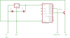
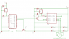
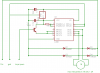
im using the l298 for it, and its in parallel mode (until 4A), i made a small board for the l298 (schematics attached), and this is my first time driving big motors, now the l298 get very hot even at 20% by the pwm (i cant touch it for more then a second) so is that normal? and i must use a heatsink? and if i do i would like it to be a small as possible so how would i know what big enough?

olso any comment on how to improve the circuit will be great, cus i made it up by myself from date sheet i dont know if its the best way....

thanksss
 

Attachments

  • 1.png
    1.png
    9 KB · Views: 1,826
Last edited:
If I calculated the power dissipation properly for 0.7A, it's either running at 40C or 80C without a heatsink. If you can touch it for a second then my guess it would be 40C (maybe?). Anyways, use a heatsink. THe only way to size a heatsink is to hunt through the thermal resistance info in the datasheet and the power dissipation of the driver, and then find a heatsink with the power dissipation and thermal resistance that you want.

Technically "being too hot to touch" is a fairly poorly measure as to how hot is too hot for drivers (a lot of them can run at 85C and even higher which is quite a bit too hot for a human anyways).
 
Last edited:
Also there is a difference between the temperature of the die and the case. You can calculate the difference from the figures on the datasheet.
 
thx for ur replays so il get a heatsink on it, but i have a different problem.
the pic is controlling the motor by pwm and as you can see it totally isolated from the pwm circuit not even applying the pwm directly rather then by the tip41 transistor. it has its own 5v regulator and is getting only the 15V... but strangely the pic circuit is influeced and for example when i blink leds at a rate it makes them act very strangly like turn on and off and blink at will or turn slightly on.

the only common spots for the 2 circuits are the 15V the GND and the PWM output, and i have the diodes there and the caps, and still its effecting the circuit somehow, the pic circuit has a its own voltage regulator.
when i run the system without the motor unit it works ok but with it strange things happen.

pic circuit attached below. and btw its happned also when simply conected a single 5V led with a resistor to the pic....

help meh thakzz
 

Attachments

  • 2.png
    2.png
    6.5 KB · Views: 665
it dose when it with the full circuit with picture1 up there in my first post heres the full diagram with few corrections.
 

Attachments

  • 12.png
    12.png
    14.4 KB · Views: 868
I M Trying To Build One Line Following Robot.
I Have Used L298 And Two Motors Of 200 Rpm,at89c51 Lm324.
All The Connections Have Been Made.but I Am Stuck With The Connections Of The L298 And The Motors.i Have Used Pin No.1,pin No. 2 Of My Microcontroller As The Outputs From It.please Illustrate Me Each And Every Connection Of L298 And The Connection From The Microcontroller To The Different Pins Of The L298.

Hoping To Hear A Quick Response.

Thanking You.

Chandan Tiwary
 
Hello there,


One problem i see right off with that circuit is that you are using
diodes 1N4007. These are not made for PWM applications.
If your PWM frequency is over 60Hz (that's 60Hz and not 60kHz)
then you should be using Schottky or other high speed diodes.

The extra capacitance puts a greater load on the L298 transistors
and will cause extra heating at frequencies greater than about
400Hz.

If you are running at a lower frequency like 100Hz it might not matter,
but the Schottky's are better diodes anyway.
The part number that comes to mind is 1N5822 or similar.

There may be other problems as i havent looked at the entire circuit yet.
 
In the first schematic:
1) Both ICs do not have a supply voltage. Shouldn't it be +15V?
2) The ground of the circuit is not connected to the ground of the power supply and input.
3) The inputs of the L298 never go low because a resistor or something to ground is missing.
4) One terminal of the motor is connected to output 1 and output 4 of the L298 but these outputs have no inputs.
5) The 47k resistor feeding the enable inputs has a value that is way too high. Try 1k or a piece of wire.
 
You should be using schottkys and not junk rectifiers for starters. "Big motors" is a relative term, I am used to dealing with integral horse motors- 1-3KW drive electronics.

Dan
 
If I calculated the power dissipation properly for 0.7A, it's either running at 40C or 80C without a heatsink.
80C rise for 105C junction. with out a sink. Paralleling helps very little only dropping Vsat from 2.1V to 2V.

In short, the IC is a piece of crap by todays standards. He needs to select a FET based IC.

Dan
 
Last edited:
Hi Ubergeek
You can give me your schematic, maybe i can find some thing..!!
Well as a commercial design I can not post the whole thing. I can certainly help with power component choices and control techniques.

I do not remember the exact parts off hand, but I know we are currently using 600V 50A IGBTs for 220V systems and 250V 50-100A FETs (I do not remember exactly) for 110V systems. All are super TO247s on heatsinks since they dissipate 30-50W on the power switches as well as on the freewheeling diodes, and rectifier bridges. Of course these are driving 15A continious into a 110V motor and more at low speed.

Dan
 
I dont understand why it still overheat, while i see it operates very good, not overheat.:confused:
Maximum junction temperature: 130C
Thermal resistance junction to ambient: 35C/W with out a heat sink
Saturation voltage: 2.5V
Motor current: 0.7A
Ambient temperature: 30C ?

junction temp = 2.5V * 0.7A * 35 + 30 = 90C not including switching losses.

Marginal at best.

Dan
 
If you can touch it for a second then my guess it would be 40C (maybe?)

"People of all ages can be
burned in 30 seconds by a flowing
liquid that is 130° F; at 140° F, it takes
only five seconds; at 160° F, it only
takes one second.

For children under
5 (these aren't people?), these temperatures can cause a
burn in half the time."

Easy way to convert C to F or backwards, from a magazine article in the 70s. The first step is the opposite of the last and there are 3 steps.

1. Add 40 to either C or F
2. To go from C to F multiply by 9/5; otherwise by 5/9
3. Subtract 40.
 
Last edited:
Status
Not open for further replies.

Latest threads

New Articles From Microcontroller Tips

Back
Top