I need to run a small dc motor (4.5v) with a sound detection module
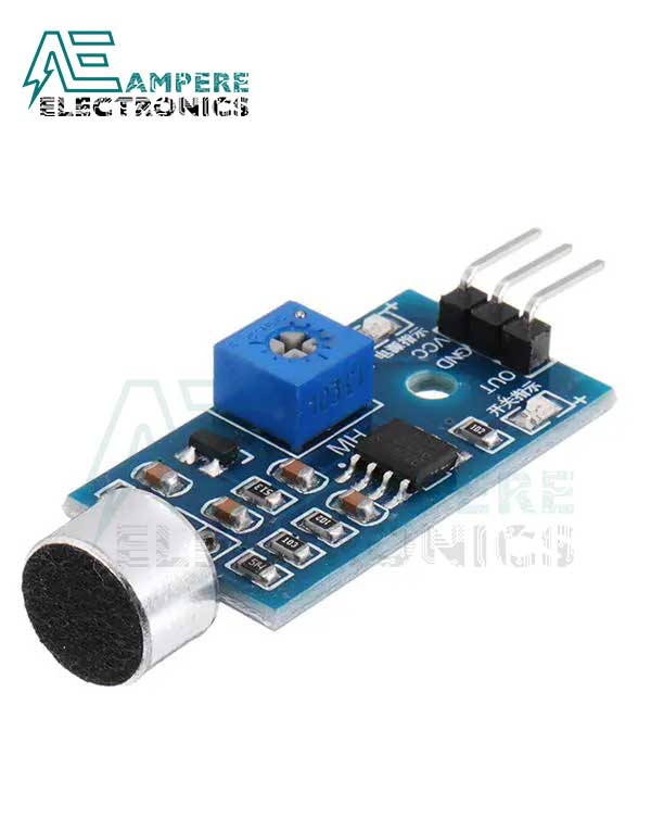
Shown here.
 I don't know how to connect up the digital output pin to drive the motor and it appears that this output varies in voltage from around 2.8 to 3.2 volts which makes the motor run too slow at times. I need the motor to be either off, or full on at 4.5 volts. To complicate matters, the output measures full voltage with no sound and then with sound goes low from 2.8 and up. Searching the internet for info on this module only turns up connections to an arduino which I don't want to use. I'd like to use a minimal of discreet components like a transistor etc.
Any help would be greatly appreciated.
Shown here.
Any help would be greatly appreciated.